Skip to content
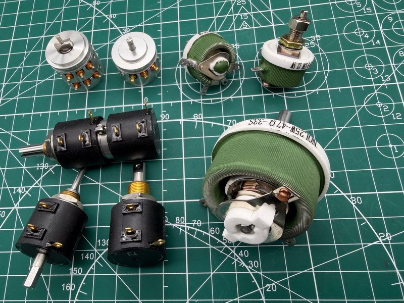
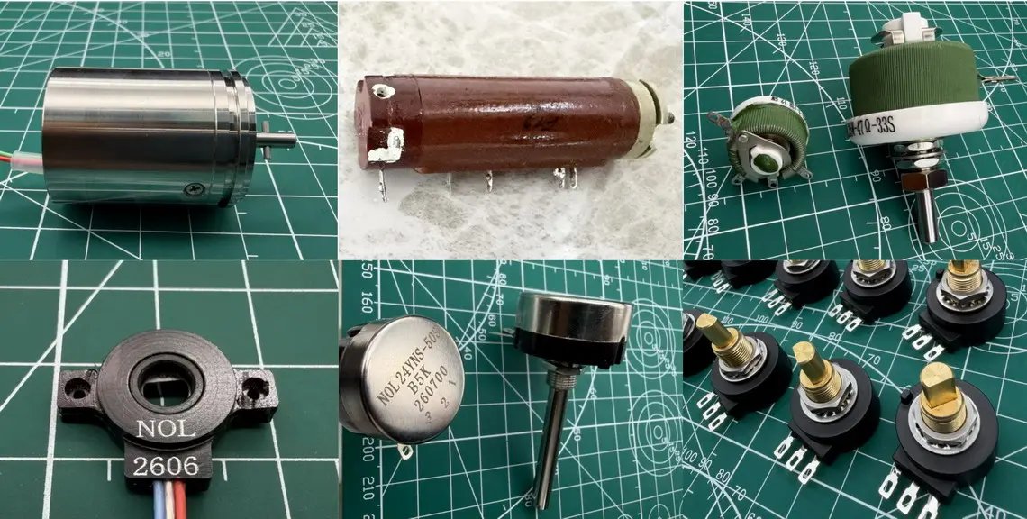
The image above shows several precision wirewound potentiometers, including dual-gang models.
I previously wrote an article titled What Is a Servo Potentiometer?, which briefly explained its applications and basic operating circuit principles.
The idea for this article came to me while organizing some component photos. I suddenly remembered a custom industrial dual-gang wirewound potentiometer project from about eight months ago.
Our costing team gave me an unbelievably high quotation. I spent at least two days thinking about it before sending it to the customer. I was genuinely afraid the customer might come after me with a knife when he saw the price.
Looking back, though, our costing team wasn't being unreasonable.
There were two main reasons:
- First, the customer needed a very small quantity.
- Second, the product was a replacement for a heavy-duty dual-gang wirewound potentiometer, requiring a complete set of new tooling.
More importantly, wirewound potentiometers have a particular manufacturing challenge: some film-based potentiometers can undergo laser trimming after the resistive track is formed, allowing local resistance distribution and linearity to be adjusted. Wirewound potentiometers do not offer the same flexibility for post-production correction.
For wirewound potentiometers, the resistance wire material, diameter, winding pitch, and mechanical structure determine much of their electrical performance during manufacturing.
That's what we're going to explore.
What Are the Differences Between Film-Based and Wirewound Resistive Tracks?
Before discussing manufacturing difficulties, let's make a simple comparison.
| Comparison | Film-Based Resistive Track | Wirewound Resistive Track |
|---|---|---|
| Common materials | Conductive plastic, carbon film, cermet | Resistance alloy wire |
| Resistive structure | Continuous resistive film | Wound metal resistance wire |
| Total resistance control | Material formulation, film thickness, track geometry, and trimming | Resistivity, wire diameter, and total wire length |
| Linearity control | Film uniformity, track geometry, and applicable trimming processes | Winding distribution, material consistency, and mechanical precision |
| Local adjustment after manufacturing | Some structures allow laser trimming | Very limited adjustment |
| Output resolution | Generally provides smoother, continuous output | Affected by discrete wire turns and contact structure |
| Main manufacturing challenges | Film uniformity and electrical performance adjustment | Winding precision, material consistency, and mechanical alignment |
It should be noted that not all film-based resistive tracks are suitable for laser trimming. The possibilities depend on the material and manufacturing structure.
Likewise, wirewound potentiometers are not completely impossible to adjust after manufacturing. However, correcting local resistance distribution is much more difficult than with a continuous resistive film.
Why Can Film-Based Potentiometers Be Adjusted by Laser Trimming?
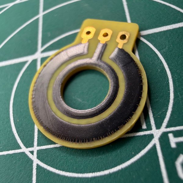
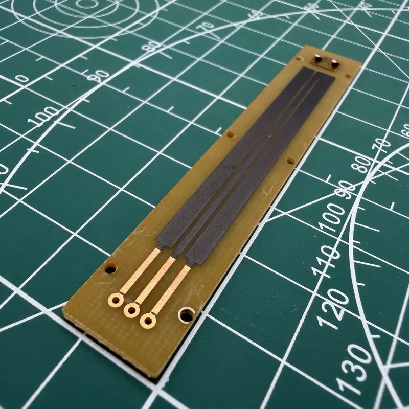
In the photo above, we can clearly see the difference between trimmed and untrimmed resistive tracks. The trimming marks vary in length and do not necessarily look uniform.
A customer once asked me whether we could make these trimming marks completely invisible while still meeting military-grade requirements.
Our answer was no. It's not that we don't want the product to look better. These marks are simply part of the resistance adjustment process.
During manufacturing, local resistance variations can occur in the film even when the same process parameters are used. By controlling the trimming position and amount of material removed, we can compensate for some of these variations.
However, there is a limitation: laser trimming primarily adjusts resistance by removing material. It cannot simply reduce local resistance that is already too high.
Therefore, laser trimming has its own adjustment limits, and not every manufacturing error can be corrected afterward.
Why Can't Wirewound Potentiometers Be Adjusted in the Same Way?
Resistive element from a multi-turn wirewound potentiometer
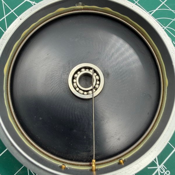
High-precision single-turn servo-grade wirewound resistive element with fine, uniformly arranged turns
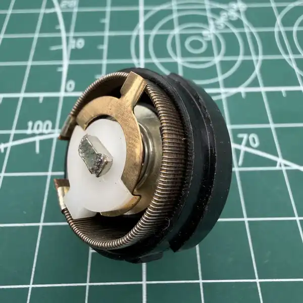
A relatively ordinary wirewound structure showing visibly irregular winding spacing
Looking closely, we can see significant differences in winding density, uniformity, and structure among these products.
Unlike film-based potentiometers, wirewound potentiometers do not use a continuous resistive film. Instead, their resistive tracks are made from resistance alloy wire.
The wire is typically wound around an insulated former, creating a resistive path that can be contacted by a wiper.
The resistance of the wire depends on three basic factors (don't worry too much about the formula below. I don't particularly enjoy looking at it either, so feel free to skip straight to the conclusion):
R = ρL / A
Where:
- R: Resistance
- ρ: Resistivity of the material
- L: Length of the resistance wire
- A: Cross-sectional area of the wire
In simple terms, with the same material resistivity, a longer wire or a smaller wire diameter produces higher resistance.
The total resistance of a wirewound potentiometer can be controlled by selecting different resistance alloys, wire diameters, and winding lengths.
The problem is that once the winding is completed, the position and length of each section of wire are essentially fixed, making local corrections very difficult.
Furthermore, the wirewound structure does not provide the same flexibility for trimming as a continuous resistive film.
For conventional high-precision wirewound potentiometers, we cannot simply use laser trimming to make local adjustments to the finished resistive track.
This means that errors in local resistance distribution during winding are often difficult to correct once the component has been completed.
The Real Challenge Is Linearity, Not Just Total Resistance
This is the key to understanding why high-precision wirewound servo potentiometers are so difficult to manufacture.
Suppose we need to manufacture a linear wirewound potentiometer with a total resistance of 5kΩ and an effective electrical angle of 300°.
Ideally, the relationship would look like this:
| Mechanical Angle | 0° | 60° | 120° | 180° | 240° | 300° |
|---|---|---|---|---|---|---|
| Cumulative Resistance (kΩ) | 0 | 1 | 2 | 3 | 4 | 5 |
In actual winding production, even if the total resistance measured between the two ends is exactly 5kΩ, the resistance at intermediate positions may not match these ideal values.
For example, at 120°, the measured cumulative resistance might be 2,030Ω instead of the ideal 2,000Ω.
This indicates a deviation from the ideal resistance distribution at that position.
What Does the Precision of a Winding Machine Actually Affect?
For high-precision servo potentiometers, winding equipment must control not only the placement of the resistance wire but also winding tension and positioning accuracy.
Here are three main factors:
| Control Factor | Main Influence | Potential Problems |
|---|---|---|
| Winding pitch | Affects the spacing of wire turns and local resistance distribution | Uneven pitch may cause inconsistent resistance changes at different positions |
| Winding tension | Affects the stability of wire placement | Insufficient tension may cause loose or displaced turns; excessive tension may damage the wire, insulation, or former |
| Former and mechanical structure | Affects winding position, track geometry, and wiper contact | Dimensional errors and deformation may affect output stability |
Winding pitch is one of the easiest factors to observe.
In certain winding structures, if the turns are too closely spaced in one area and too widely spaced in another, the resistance change per unit of mechanical travel may become uneven.
One easily overlooked point is that even perfectly uniform winding pitch does not guarantee the required linearity. The winding machine controls only part of the manufacturing process. The electrical properties of the wire itself, along with the wiper and mechanical structure, also affect the final output.
So, let's move on.
Resistance Wire Material and Diameter Also Determine Manufacturing Limits
Besides equipment precision, the resistance wire itself is another important factor.
Even with the same winding equipment, different materials may behave differently during manufacturing.
| Material Factor | Influence on Electrical Performance |
|---|---|
| Wire diameter | Determines the cross-sectional area and directly affects resistance per unit length. Changes in diameter do not produce a simple proportional change in resistance |
| Diameter consistency | Variations along the wire may cause differences in local resistance |
| Resistivity | Determines resistance for a given length and cross-sectional area. Consistency within the same batch and along the entire wire length must be considered |
| Material consistency | Changes in resistivity and material properties may affect resistance distribution within and between batches |
| Temperature coefficient | Affects resistance stability as temperature changes |
| Mechanical properties | Affect wire deformation, tension tolerance, and reliability during winding |
You may have noticed that I've been using the term "electrical performance" throughout this section rather than saying these factors directly determine linearity.
That's because final linearity depends on multiple factors. It cannot simply be attributed to wire diameter, resistivity, or winding machine precision.
The winding equipment controls how the wire is arranged, while the wire itself determines the electrical characteristics of that arrangement.
Both must be properly controlled to achieve a stable resistance distribution.
Why Don't Ordinary Wirewound Resistors Have the Same Strict Requirements?
Ordinary wirewound resistors or potentiometers are mainly used for current, voltage, or power adjustment. Servo-grade wirewound potentiometers, on the other hand, are used for precision position feedback, where every mechanical position must correspond to a specified electrical output.
Why Is Improving Linearity from 1% to 0.1% More Than Just a Tenfold Increase in Machine Precision?
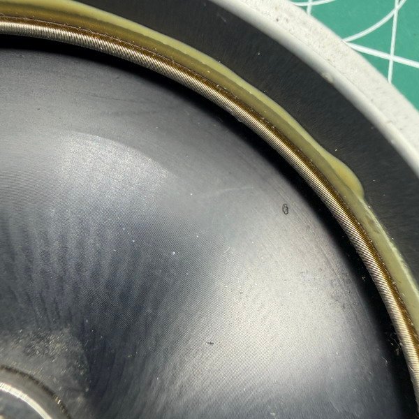
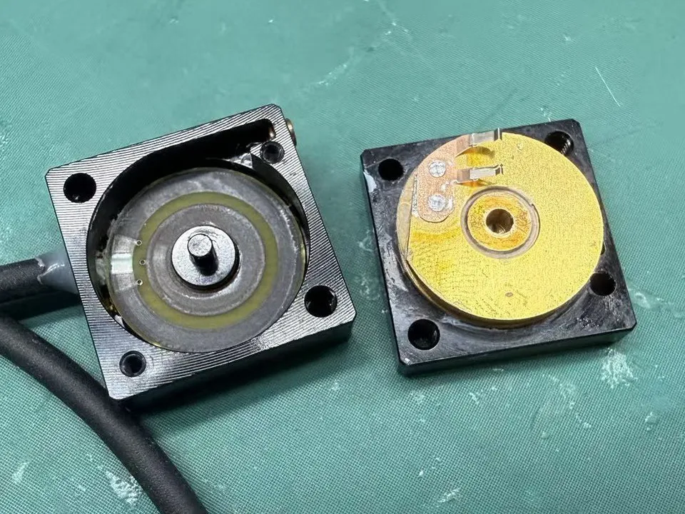
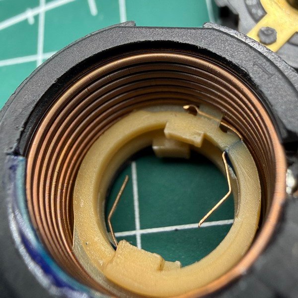
Internal structure of a precision wirewound resistive element, showing fine and closely spaced resistance wire with high winding consistency.
As we can see in the disassembled component, the resistance wire is arranged in very fine, closely spaced turns. But precision wirewound potentiometers are not simply about making the windings look neat.
Wirewound potentiometers use discrete wire turns, which creates an inherent limitation in output resolution. As the wiper moves along the track, the output may change in small steps related to individual turns rather than varying perfectly continuously.
The number of turns, resistance per turn, and wiper contact structure all affect the actual output. This is one reason why some precision wirewound potentiometers require finer resistance wire, more turns, or special winding structures.
Multi-turn structures can provide a longer adjustment travel and, under suitable conditions, finer adjustment. However, having more turns does not automatically mean better linearity.
Therefore, improving linearity from 1% to 0.1% is not simply a matter of making the winding machine ten times more precise. The materials, winding process, and mechanical structure must all work together to meet stricter requirements.
Testing Is Still Essential
Because wirewound resistive tracks offer limited opportunities for local correction after manufacturing, process control is especially important.
Testing can help us identify errors, but that does not mean we can always correct them in a finished component.
And here comes another headache. I really don't feel like going into all the testing details, because no matter how much a manufacturer says about its own testing, what ultimately matters is whether the product passes the customer's actual tests.
Final Note
When dealing with customers, we often receive questions that are surprisingly difficult to answer in just a few sentences.
For example:
Why are your wirewound potentiometers so much more expensive when they all use resistance wire?
Why are the trimming marks around film-based resistive tracks different in length and arranged unevenly?
These questions involve the internal materials, manufacturing processes, and precision control of potentiometers. They are difficult to explain in a short email.
That's one of the reasons we continue writing technical blog articles.
Wirewinding technology itself is nothing mysterious. After all, wirewound resistance technology has a long history of industrial use and was already widely adopted in the first half of the 20th century.
For us at NOL, as a manufacturer, what really matters is this:
Can the potentiometer deliver stable, repeatable electrical output that meets the customer's requirements throughout its entire effective travel?