Skip to content
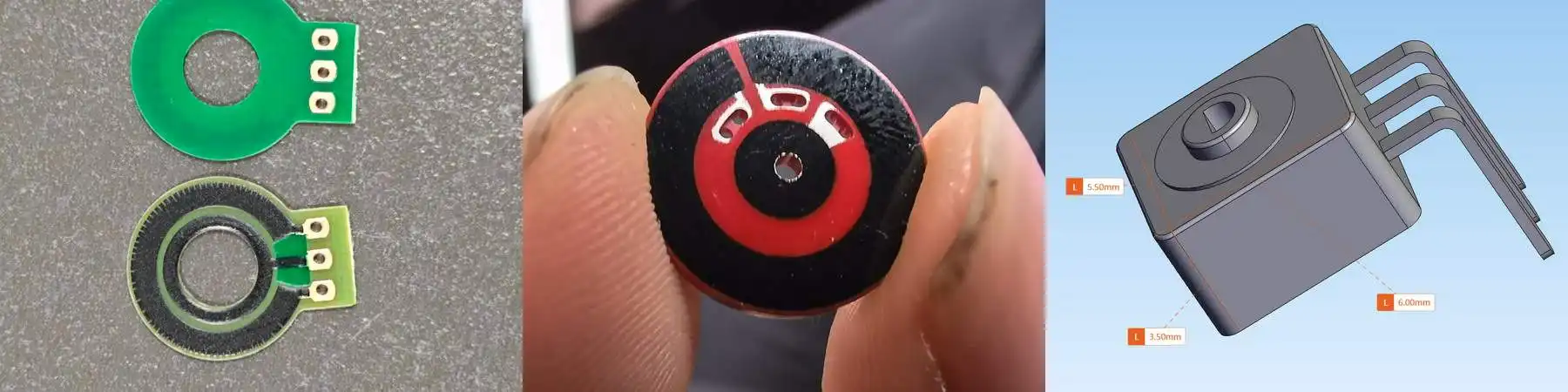
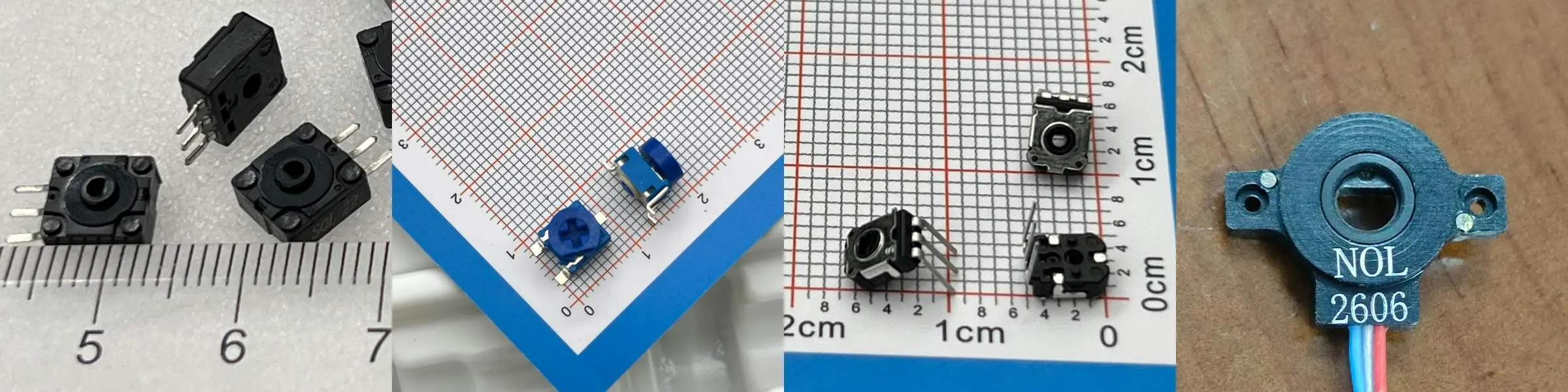
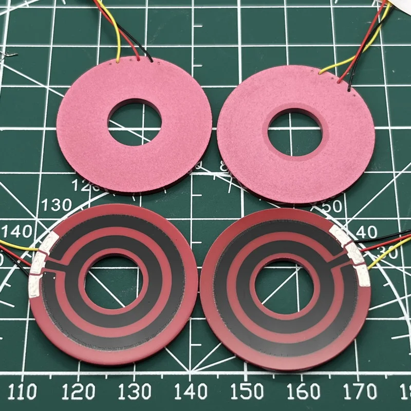
From left to right, the images show:
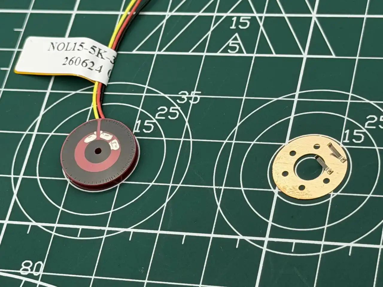
Figure 1 shows a 10 mm OD carbon film resistive track. Linearity trimming has already been completed, and the linearity is 0.5%.
Figure 2 shows a 15 mm OD conductive plastic resistive track. Linearity trimming has not yet been performed.
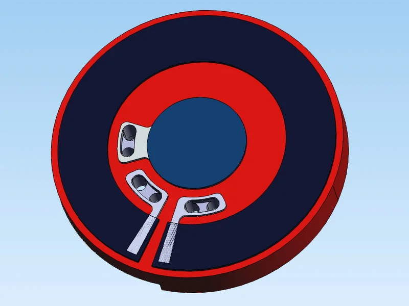
Figure 3 shows a concept drawing of an angle sensor with an outer side length of 6 mm. At least two customers have said something similar before: “If you can make it this small, then it meets our requirement.”
Introduction
Recently, I have been slightly broken by some miniature angle sensor requirements for drones and robots.
Here we are mainly discussing contact-type angular position sensors with clear performance requirements.
This size is a limitation of NOL’s own manufacturing process. I am sure someone else can do better than us.
At the beginning of this article, I take out the resistive tracks so that everyone can compare them more directly. We will roughly break this down from several important parameters:
- Resistive track width
- Linearity
- Wiper width
- Reasonable lifetime
In Most Cases, the Minimum Resistive Track Width of Carbon Film or Conductive Plastic Film
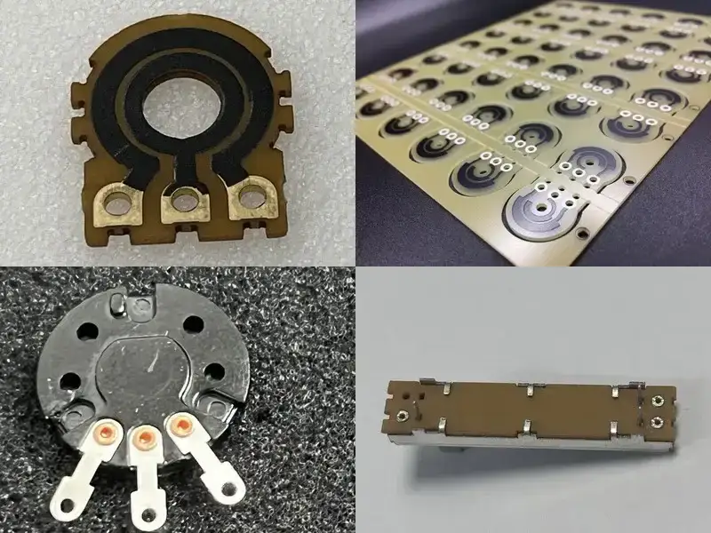
Carbon Film Resistive Track - Printing Process
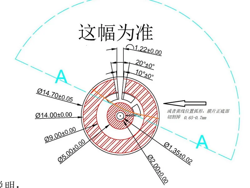
For carbon film resistive tracks, we usually pay attention to the following dimensions:
- Minimum width of the carbon film resistive track: about 0.9 mm, of which about 0.3 mm may need to be reserved for linearity trimming
- Minimum width of the silver layer circuit: about 0.3 mm
- Recommended minimum spacing between tracks: about 0.3 mm
Just looking at the data above, you will find:
Making a miniature angle sensor with an outer side length of around 6 mm seems possible. But do not rush. Let me explain, or maybe defend myself.
For this kind of very small outer size, the resistive track material can usually only be carbon film. This is because the processing method of conductive plastic film is different. It uses a co-molded process, which is somewhat similar to an impregnation or wetting process. When the size becomes too small, short circuits between tracks are more likely to occur.
Conductive Plastic Resistive Track and Silver Track - Co-Molded Forming
Conductive plastic film, which we often call a CP resistive element, generally needs more space for both the resistive track and the silver track.
According to our experience, the more reasonable dimensions are usually:
- Resistive track width: about 2.5 mm
- An additional 0.2–0.3 mm needs to be reserved on the outer side to meet the need for linearity trimming
- Track spacing: about 2 mm
- Silver layer width: about 2.5 mm
This is also why, if conductive plastic products want to balance performance, lifetime, and process stability, we generally recommend a structure of about 15 mm or even larger.
The advantages of conductive plastic film are obvious: longer lifetime, more stable output, and better suitability for high-performance sensors.
But its cost is also very direct:
It needs more structural space.
Why Not Use a Single Track?
A university research lab once asked this question. Customers ask:
“Is a single track not possible? This can reduce cost and also reduce size.”
But the problem is: a single-track structure is not good for ensuring signal stability.
I discussed this issue in another article before. I also turned part of the email content into an article at that time. I will not expand on it here. If you are interested, you can read:
Why High-Performance Angle Sensors Usually Should Not Use a Single-Track Structure
Linearity: One of the Important Conditions That Determines Accuracy
Let’s first use a 10 mm carbon film element as an example. These are its real parameters, and it happens to be something we worked on recently:
- Linearity: 0.5%
- Effective electrical angle: 270°
If we estimate based on the 9.5 mm center circle diameter of the resistive track:
The full circumference is approximately:
π × D ≈ 3.1416 × 9.5 ≈ 29.85 mm
The effective resistive track length is approximately:
29.85 × 270 / 360 ≈ 22.39 mm
A linearity requirement of 0.5% is equivalent to dividing the full travel into:
100 / 0.5 = 200 parts
Then each effective independent electrical travel is approximately:
22.39 / 200 ≈ 0.112 mm
This width is actually close to the diameter of a thicker human hair.
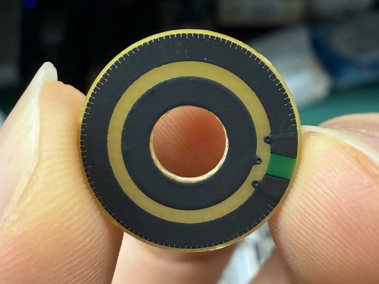
If you look at the carbon film resistive track in the figure below, where linearity trimming has already been completed, you will find that the trimming points are relatively many and evenly distributed. This is because the diameter is small, and the process is more difficult to control.
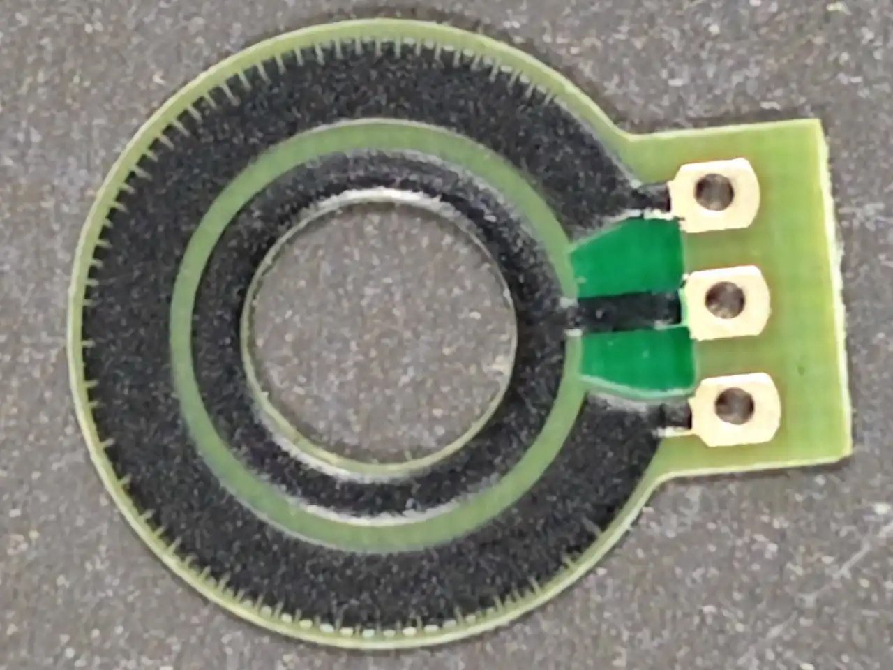
These trimming points are not decoration. They are used to make the output signal as uniform as possible.
Obviously, the smaller the size, the more difficult linearity adjustment becomes.
Why Do We Usually Recommend Conductive Plastic Products to Be at Least Around 15 mm?
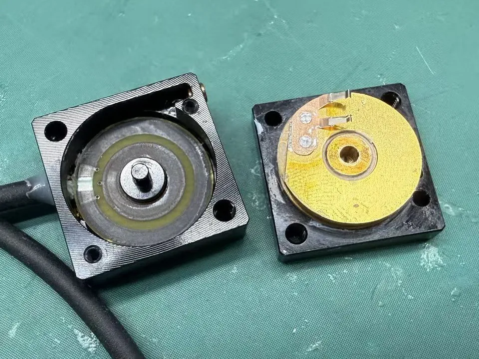
Look directly at the trimmed resistive element in the figure below. Does it feel very similar to the previous picture? But the surface smoothness of the conductive plastic product is obviously higher.
However, conductive plastic film is not suitable for being excessively compressed in size.
For example, TE’s M150 string potentiometer is described in public documents as one of the world’s smallest products. The diameter of its core resistive element is almost 15 mm.
Since TE is already there, I will not explain too much.
TE M150 string potentiometer reference document
Lifetime: It Is Related to Material, Contact Width, and Process
Lifetime is usually related to several factors:
- Resistive material
- Wiper material
- Contact width
- Contact pressure
- Actual working environment
I will first talk about it based on material, because the lifetime difference at the material side is more obvious.
For carbon film products, a reasonable lifetime target can be roughly regarded as around 1 million cycles.
For conductive plastic film products, the lifetime limit can be higher. In theory, it can reach the 10 million cycle level. But when it comes to actual miniature products, many high-performance products more commonly specify around 5 million cycles. If you do not believe it, look at the TE M150 datasheet mentioned above.
Corresponding to the size discussion above, we can roughly understand it this way:
For a 10 mm class carbon film angle sensor, achieving 1 million cycles is a relatively realistic target.
For a 15 mm class conductive plastic angle sensor, achieving 5 million cycles is more reasonable.
To put it directly:
When considering the structure, please leave a little more space for the sensor whenever possible.
Wiper Width: Another Threshold That Small Sensors Cannot Avoid
Besides the resistive track itself, the wiper is also a key part that determines performance and lifetime.
According to NOL’s current experience, for this kind of miniature contact-type angle sensor, a more reasonable precious metal wiper contact width is usually:
0.8 mm or 0.9 mm, roughly as shown below:
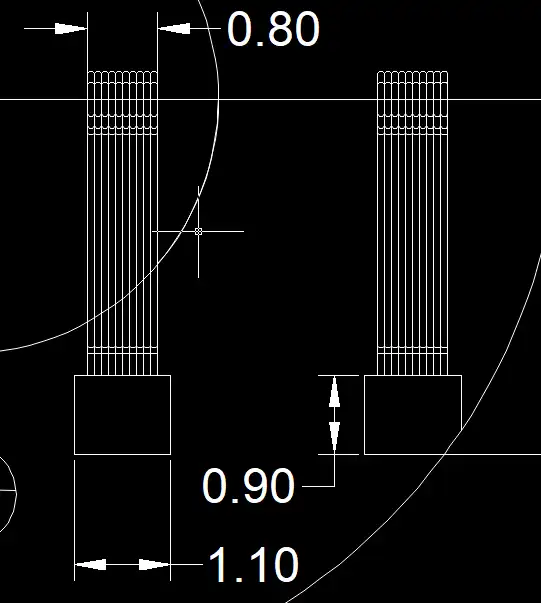
This size range makes it easier to balance performance, lifetime, and manufacturing stability.
Why not make it even narrower?
Because precious metal wire contacts themselves need a certain amount of arrangement space. It is not a simple metal strip. It is made of multiple wire contacts arranged in parallel.
Reducing the number of precious metal wires can reduce cost and also make the structure easier to compress.
At the same time, it will also reduce lifetime and reliability.
This is a very realistic point for small contact-type angle sensors:
Compressing space also compresses performance.
Back to the 6 mm Angle Sensor: Can It Actually Be Made?
Now let’s return to the 6 mm outer size concept drawing at the beginning.
Many customers feel that this size is very ideal when they see it.
Especially for drones, robots, and miniature actuators, the structural space is already very limited. If the outer size of the sensor can be made to 6 mm, it is indeed very attractive.
So the question is:
Can a 6 mm outer size contact-type angle sensor actually be made?
The answer is:
It can be discussed. From the perspective of carbon film process, it is not completely impossible.
But it must accept many real limitations.
Final Notes--The Pain Point of Using Extreme-Size Components in Prototype Development: Cost
Many prototype projects will face the same contradiction when they move toward actual implementation:
The end customer wants to purchase a small number of samples for verification first.
But once the production side starts the development of an extreme-size product, it may need to invest in molds, fixtures, testing, and process verification first.
Take the 6 mm outer size angle sensor above as an example.
From your point of view, even if one high-performance sensor costs two or three hundred US dollars, and the minimum order is ten pieces, the total cost of two or three thousand US dollars may still be acceptable.
But then I say: this product currently has no existing mold, and the tooling cost is about USD 20,000.
At this point, you will probably curse in your heart:
“These guys are ripping me off!!!”
But from the manufacturing side, this kind of cost often really exists.
Because the more extreme the small size is, the more it usually means:
- The mold is harder to reuse
- Process verification cost is higher
- Testing requirements are more complicated
- Yield risk is higher
- Initial demand quantity is smaller
- Development cost is harder to amortize
This is why, for many miniature high-performance sensor projects, the most painful point in the prototype stage is often not the technical discussion, but this:
The customer only needs a small number of samples for verification, but once the project starts, we have to spend almost the full development cost.
This contradiction is very real.
So, dear customers, please leave a little more space for the angle sensor!