...

Custom & Replacement High-Performance Potentiometers

Specialized Potentiometer Supplier with In-House Manufacturing and Custom Engineering

Spec confirmation → sample validation → small-batch scale-up/delivery

Typical sample lead time: ~25 days

About NOL.

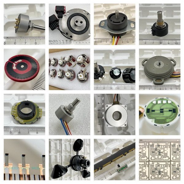
We are a mid-sized manufacturing team. We provide custom and replacement potentiometer elements and potentiometer sensors for overseas customers.
Your custom project is not limited by one factory’s processes or product range. You gain access to our in-house capabilities and qualified production partners to develop the right potentiometer solution.

What We Make, and How It Evolved

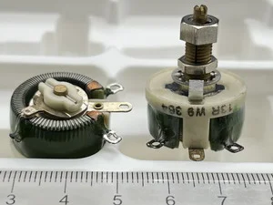
2003~ Wirewound → Multi-turn long-life

Started with wirewound potentiometers and extended to multi-turn long-life structures (up to 20 turns) for finer adjustment and stable long-term use.

2011~ Thick-film circuit & wiper (TPS as example)

Built thick-film circuits and a stable wiper contact system to improve consistency in mass production, with TPS-style structures as a typical example.

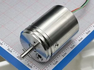
2015~ Conductive Plastic Elements & Precious-Metal Wiper

Introduced conductive-plastic resistive elements with precious-metal spring contacts. In selected designs, TCR can be as low as ±150 ppm/°C, supporting MIL-grade replacement needs.

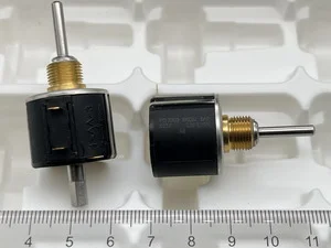
2018~ Multi-gang / stackable / special builds

Expanded into multi-gang and stackable designs, plus special builds for small-batch, multi-variant supply where mechanical interfaces and channel consistency matter.

2021~ High-performance carbon film (360 degree )

Developed high-performance carbon-film solutions (life up to 5 million cycles), offering a larger effective electrical angle and a more cost-controlled manufacturing process.

How We Confirm Fit and Move to Production

Start with your specs. End with stable deliveries.

Who We Support

• New tooling & custom builds;
• Replacement / upgrade (cost-down included);
• Discontinued part replication;
• Small-batch, multi-variant supply.

How We Confirm Fit

• Conditions: temp, vibration, sealing, media;
• Materials: CP / carbon / wirewound + wiper;
• Targets: life, linearity, TCR, torque, resistance;
• Interfaces: mounting, shaft, angle/stroke, stops.

How We Move to Production

• Input: drawings/datasheet, or photos with key dimensions (email attachment or link);
• Feasibility: material route and risk notes;
• Sample test: confirm dimensions, electrical behavior, and assembly fit;
• Small batch: first-article check + in-process checks;
• Batch delivery: delivery by batches with traceability (if applicable).

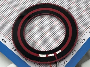
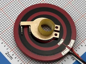
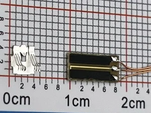
From left to right: a 10 mm carbon film resistive track with 0.5% linearity trimming, a 15 mm conductive plastic resistive track before trimming, and a 6 mm outer-size contact-type angle sensor concept drawing.

Why Are Contact-Type High-Performance Angle Sensors Usually Larger Than 10 mm in Diameter?-Written for Drone and Robotics Engineers, Part 2

For miniature drones, robots, and actuators, a 6 mm contact-type angle sensor looks very attractive. But when we look inside the sensor, the real limitations become clear: resistive track width, linearity trimming space, precious metal wiper width, lifetime, and tooling cost. This article explains why high-performance contact-type angle sensors are usually larger than 10 mm, and why 15 mm is often more realistic for conductive plastic designs.

Read More »
Through-hole trimmer, SMD trimmer, miniature potentiometer, and NOLELC 10 mm miniature angle sensor shown side by side for size comparison.

Trimmers, Miniature Potentiometers, and Miniature Angle Sensors: What Is the Real Difference?

Many small contact-type components look similar, especially trimmers, miniature potentiometers, and miniature angle sensors. For drone, robot, and prototype design, this confusion can lead to the wrong space reservation and poor angle feedback performance. This article explains why the final sensor selection should focus on usable electrical angle, resistive track space, wiper contact, output stability, and realistic manufacturing limits.

Read More »
13.6mm-circular-carbon-film-resistive-element-linearity-trimmed-crv-tested

How to Verify a Factory’s Manufacturing Capability and Product Performance at Lower Cost When No Existing Mold Is Available

For low-volume custom sample projects, reopening a full tooling set at the beginning is not only a technical issue, but also a cost decision. Using a circular membrane resistive element as an example, this article explains how to lock the effective arc length, total resistance, and matched contact relationship first, then use existing tooling to verify linearity, CRV, and the factory’s real manufacturing capability.

Read More »
front view, back view, and wiring layout of a 6915 conductive plastic resistive element

Conductive Plastic Resistive Elements: The Direct Impact of Substrate Manufacturing Methods on Cost

After an old customer asked for the color on both sides to be consistent, I checked again the relationship between substrate manufacturing method and cost for conductive plastic resistive elements used in potentiometers. I found that what changed was not only the mold cost, but also the later production efficiency, demolding rhythm, yield rate, lead time, and even the adjustment room at the sample stage. This article mainly discusses why the substrate manufacturing method directly affects cost.

Read More »

Get In Touch

Your information will only be used to respond to your request.
We usually reply within one business day.
If you have drawings or attachments, please email them to Cola@nolelc.com.