Skip to content
 Introduction: A 15 mm OD Project Made Me Rethink This Problem
Last month, we reviewed a small conductive plastic element project. We saw a very typical request again. The customer wanted the outer diameter to stay at 15 mm, and at the same time wanted a 340° effective electrical angle.
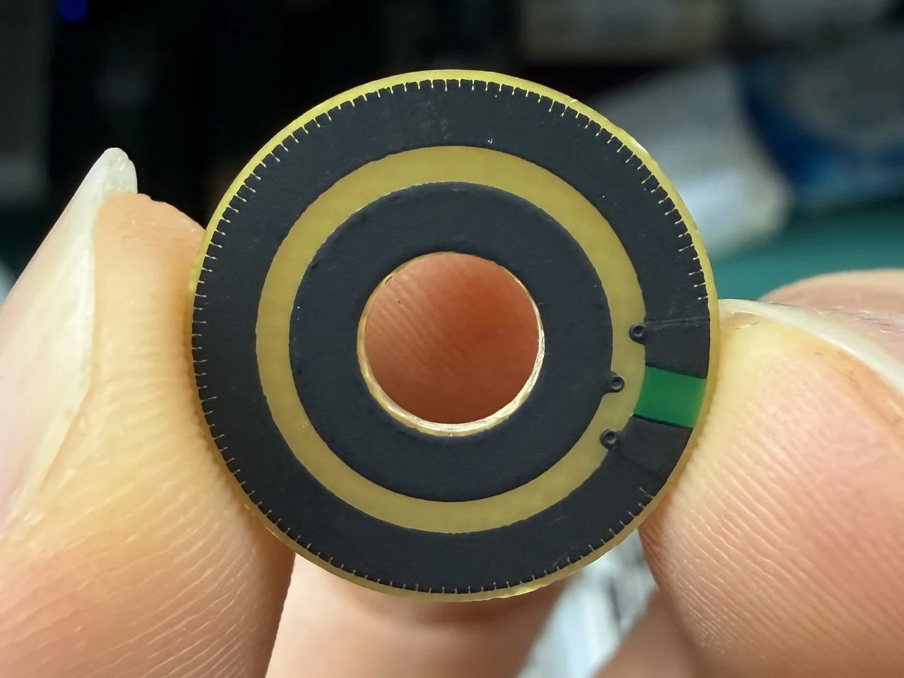
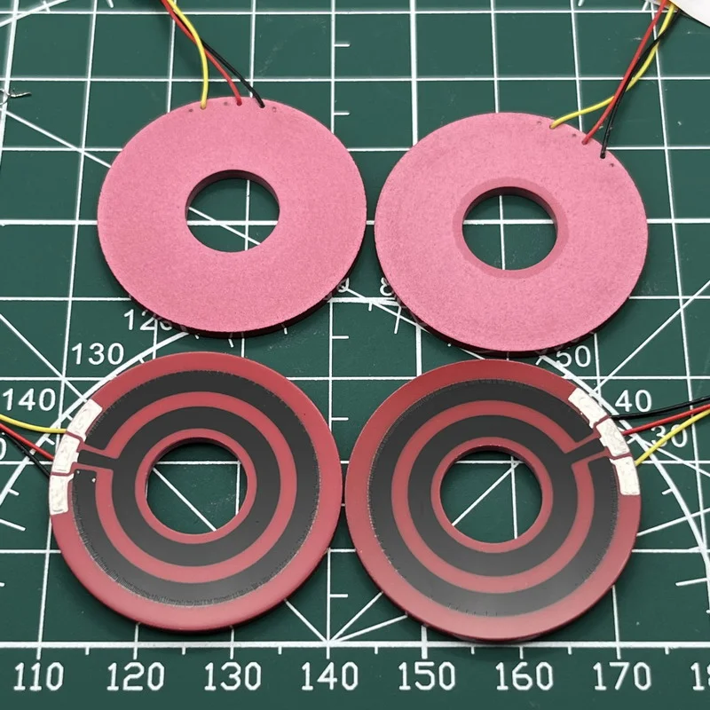
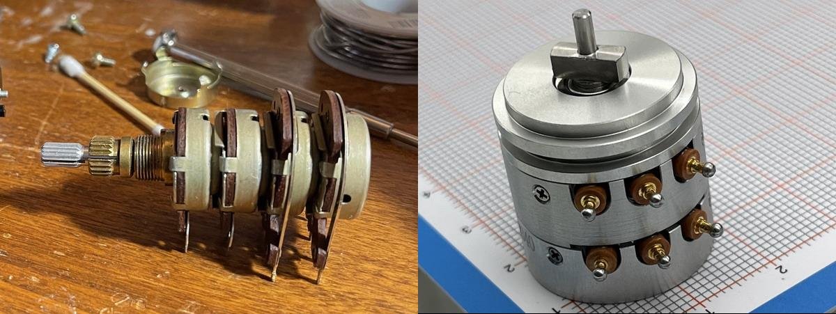
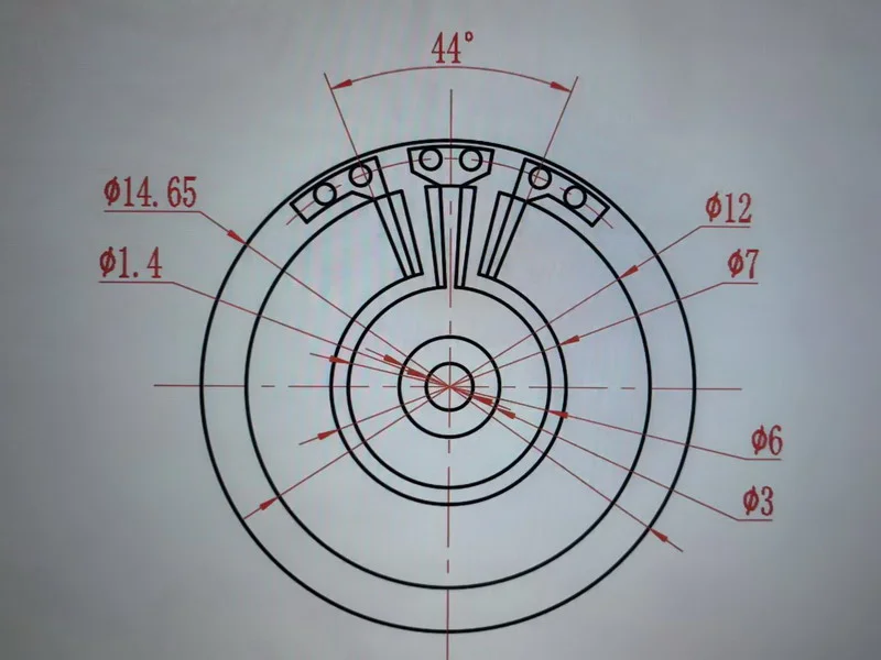
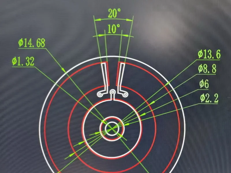
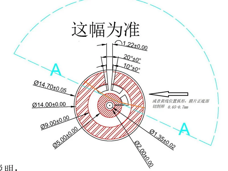
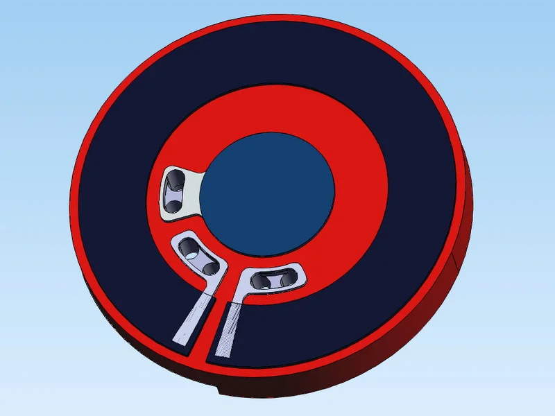
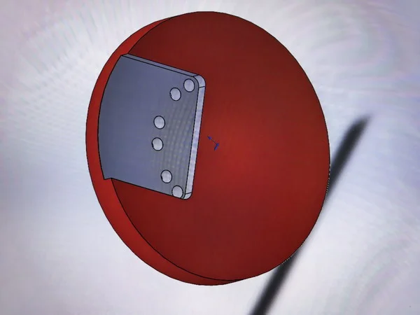
At first, I replied too quickly. I thought this target could be done. But after my colleague and I opened up the structure, terminal layout, and resistive track, we found that for this size, 316° was the stable limit. It was very hard to push it further. These images show the development process of a small-diameter conductive plastic resistive element. The original layout provided about 316° effective electrical angle, while the following designs explore how to extend the angle toward 340° within an outer diameter of around 15 mm. The comparison shows that the challenge is not only drawing a longer resistive path, but also keeping enough space for terminal connections, contact areas, and stable manufacturing.
In many cases, the real problem is not whether the drawing can be made. The real problem is whether the product can be manufactured in a stable way after the drawing is made.
I want to give the result first. We did make a workable production solution. But in the end, I did not win this order. The reasons were simple: lead time and price. What impressed me more was the customer's honesty. He told me his target price and target lead time very clearly. In the end, the price was basically accepted, but the lead time still could not match.
In this article, I will talk about four parts. First, I will explain why I am not discussing carbon film here. Then I will talk about the common large-angle range in public datasheets. After that, I will go back to manufacturing and explain why it is harder for a small conductive plastic element to get a larger effective electrical angle. Finally, I will show how we usually try to move closer to that target.
Why I Am Not Discussing Carbon Film in This Article
I do not plan to compare carbon film in this article. The reason is simple. In some structures, carbon film can use PCB printing routes and move much more easily toward 360°.
But conductive plastic is different. Its main advantages are life, smooth output, and better signal quality. Once the diameter becomes small, if we still want a larger effective electrical angle and good linearity at the same time, the manufacturing difficulty goes up clearly.
Common Angle Ranges in Public Datasheets for Conductive Plastic Products
If we only look at public datasheets, many single-turn, three-terminal conductive plastic products still stay in the 320° to 340° range. Some larger or higher-grade products can reach about 350°. In the market, we can also see wording like “up to 355°”. But almost nobody gives 360° as a standard specification for a three-terminal conductive plastic potentiometer.
In the industry, many people are familiar with platform names like 6906, 6909, and up to 6920. But in this article, I do not want to keep using these part numbers. If I use metric diameter instead, the reader can understand the relation between size and angle more easily.
We can also see this limit from the way public specs are written. Some datasheets show 340° ±5°. Some documents say “up to max. 355°”. In some military or high-reliability catalogs, we can also see 340°/344° or 350°/354°. This means the “effective angle” and the “continuous conductive angle” are not the same thing.
This detail already tells us a lot. Even in high-end product lines, some non-effective area still has to be left at the ends. The full circle is usually not used as the effective measuring area.
From NOL’s Experience, a Larger Effective Angle Usually Needs a Larger OD
When I compare this with our own manufacturing experience, the pattern becomes much clearer. Public information can show the common limit in the market. But our own work shows the real size cost behind it.
Below are some angle levels that NOL has reached before:
| Target Electrical Angle (0–X°) | Required Element OD (Approx.) | Notes |
|---|---|---|
| 0–340° | 19 mm | At OD = 23 mm, our maximum stable value was about 341.5°. |
| 0–345° | 27 mm | To reach 345°, the OD usually needs to increase to about 27 mm. |
| 0–350° | 31.5 mm | To reach 350°, the OD needs to be about 31.5 mm. We can provide photos of similar finished parts. |
| 0–357° | 46 mm | To get close to 357°, the OD needs to become much larger, around 46 mm. |
These data are important to me. They are not copied from public sources only. They come from real manufacturing experience. Because of this, when I now see a request for “small diameter + large angle”, I no longer rush to study the quotation first. I first look at the deeper limits.
Why Is It Harder for a Small Conductive Plastic Element to Increase the Effective Electrical Angle?
The Arc Length for the Resistive Track Is Naturally Shorter
When I see this kind of request now, my first reaction is not “Can we do 340°?” I first want to know two things: what is the diameter, and how much arc length can really be given to the resistive track.
For a circular film element, the arc length is π × D × θ / 360. When the diameter gets smaller, the effective path also gets shorter under the same angle. This means that end transition areas and silver connection areas that are acceptable in a larger part can become a much bigger percentage in a small part.
Many projects do not fail because conductive plastic cannot be made. The real problem is that the angle left for stable and effective output becomes smaller and smaller.
The End Area Cannot Be Pushed All the Way to the Limit
Another point is often ignored. The end area cannot simply be pushed all the way to the limit.
This is related to the processing method of conductive plastic itself. For example, with impregnation-type processing, the final surface can look flat, but if the end area is pushed too far, unwanted connection can easily happen. In serious cases, the element can even fail. A three-terminal voltage divider potentiometer must have a start point, an end point, and a lead-out connection. Once there is terminal connection and wiper entry and exit, a transition area will exist at the ends.
So when public specs show 340° effective angle with 344° continuous conductive angle, or 350° with 354°, they are telling us the same thing: in theory, conduction may continue, but that part is not the same as a high-quality and controllable measuring area that can be sold as effective output.
For a small conductive plastic element, this limit becomes more obvious, because the usable circumference is already shorter.
In Many Cases, the Real Limit Comes from the Wiper, Not the Resistive Layer
The third limit often comes from the wiper, not from the resistive layer itself.
First, the wiper usually needs a minimum contact width. Based on NOL’s normal requirement, it is usually 0.09 × 9, which means at least about 0.8 mm. This is needed to keep current or signal stable in a safer way.
If a small part only tries to get more effective angle by pushing the track closer to the ends, and at the same time making the track narrower, then the resistance density also has to change. On paper, this may create some more degrees. But the side effects also come with it. For example, linearity becomes harder to control, and CRV also becomes harder to control.
So the point is not that a small conductive plastic element cannot reach a larger angle. The point is that this must be done only when performance can still be protected.
I also want to add one more point. The quality of the precious metal wire used in the wiper also matters. It is not enough that it looks similar. Similar appearance does not mean the same signal performance, wear result, or life result.
If We Still Need a Larger Angle, How Do We Usually Adjust the Structure?
So if a small conductive plastic element still needs a larger effective electrical angle, and also needs to fit into a limited installation space, what kind of structure do we usually end up with?
Try to Get a Larger Effective Circular Diameter
The first and most direct step is still to get as much effective circular diameter as possible. Even if the outer diameter cannot become much larger, the center hole, mounting clearance, and insulation boundary may still have some room to adjust. Even a small increase in the average track radius can help a lot after it is converted into arc length.
For small parts, the blank substrate area near the outside is usually compressed as much as possible. Based on our experience, it can even be controlled to about 0.5 mm from the outer diameter radius difference.
Move the Silver Track Connection Point Toward the Middle of the Dual Tracks
The next step is to improve the silver track connection position.
One workable way is to move the silver track connection point as much as possible into the middle area of the dual tracks. In this way, the usable outer diameter space is almost fully used. For a small platform, this step is very important. It is not just a small routing change. It is a real way to squeeze out more usable arc length.
But this also creates a new problem. The middle terminal connection may stick out, and then it may affect the mounting space. In other words, you gain some angle, but then you get a new installation problem.
Use Post-Cutting to Create a Lead Wire Channel and Keep Mounting Space
So the next step is to combine this with post-cutting. In this way, we create a wire channel and leave room for installation.
NOL has used this type of process idea when reaching close to 350° on the 31.5 mm platform, and also when pushing a 15 mm platform toward a larger angle. Because of this, I now feel more strongly that for this kind of project, we cannot only look at one angle number. We also need to see whether the full structure really works as one complete solution.
Why I No Longer Easily Say “Yes, We Can Do It”
After going through projects like this, I no longer easily tell customers that a small diameter and a large effective electrical angle will definitely be no problem.
In the public market, the more common range is still 320° to 340°. There are real manufacturing reasons behind this. In many cases, it is not that people in this industry do not want to push further. It is that once we push further, stable manufacturing, performance balance, mounting fit, and cost control all come out at the same time.
If a customer really wants a larger effective electrical angle in a small diameter, I think it is better to break the problem into smaller questions first:
- Must the original outer diameter stay unchanged?
- Is large angle the first priority, or is linearity the first priority?
- Are there some structure details that still need clearer discussion?
In many cases, the solution is not impossible. But the complexity cannot be removed by only saying, “Yes, I can do it.”
Final Notes
For a factory like NOL, which has worked on replacement and custom products for a long time, this kind of judgment is actually more important than only giving a quotation, or only saying “it can be done.” What the customer really needs is not just a solution with nice numbers on paper. The customer needs a solution that can be installed, can give stable output, and can also stand on the manufacturing side.
When I look back at this 15 mm project now, my own feeling is very direct. I no longer want to answer too quickly whether it can be done. I would rather explain the limits first, and then talk about price and lead time. Because making the limits clear is also part of being responsible to the customer.