Skip to content
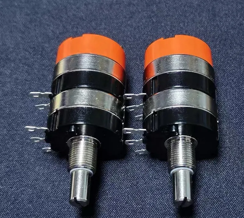
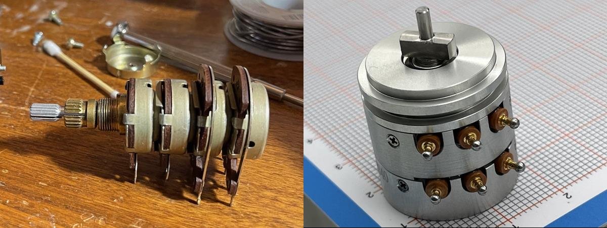
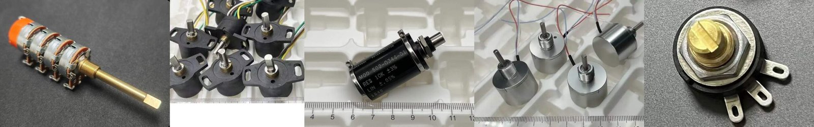
Two stackable multi-gang panel-mount potentiometers (solder-lug terminals), often used for multi-channel control or signal adjustment when space is limited.
Let’s start with a question: Why use a “multi-gang single-control” design instead of several single-gang units?
Introduction: The most direct value of a multi-gang, single-control potentiometer is simple. One knob (one shaft movement) can drive multiple independent circuits at the same time. To the user, it feels like “one motion adjusts several knobs,” but the panel only needs one knob. This structure is common when space is limited and operation must stay simple. You do not want the user to adjust A and forget B. You also do not want repeated back-and-forth adjustments just to align settings.
More importantly, the relative relationship stays stable. When we use two separate single-gang units to “sync” two channels, over time, knob position, assembly angle, and feel differences often make the sync turn into “by feeling.” With a multi-gang single-control design, the input is coaxial. At least at the operation level, one action happens to multiple circuits at the same time.
1) What do “multi-gang,” “single control,” and “stackable” mean?
- Multi-gang: One shaft drives multiple independent resistive units. Each gang can be seen as a complete small potentiometer module, with its own resistive element and wiper system.
- Single control: There is only one shaft/knob input. Turn it once, and all gangs move together.
- Stackable / modular: Each gang is a “module section,” and the number of gangs can be stacked as needed. A common structure is: through-shaft + segmented housing/spacers + one resistive element per section + one wiper per section.
I often explain it to customers in one sentence: multi-gang single-control means “one shaft, multiple independent circuit outputs.” Stackable means “the gang count can be assembled based on need.” Once this is clear, the “options” become easy to describe. Gang count, resistance value, taper, and material route can all be combined at the per-gang level.
2) Key design points: Multi-gang is not the same as simply stacking modules
Many people first hear “stackable multi-gang” and assume it is just stacking modules together. In real projects, the pitfalls mainly fall into four areas: mechanical, electrical, consistency, and life.
I put these four areas into a table for quick reading:
Below is a quick table of the four common “pitfall areas” in stackable multi-gang designs:
| Area | Why it becomes sensitive | Typical risks / misunderstandings |
|---|---|---|
| Mechanical | More gangs increase axial length sensitivity, end-face clamping sensitivity, and coaxial alignment risk. Module tolerances stack up. Torque usually increases with gang count. | Feel consistency becomes harder. Many gangs + “light feel” often forces trade-offs in wiper design, spring force, lubrication, and clamping method. |
| Electrical | Each gang is an independent circuit, but they sit very close physically. Inter-gang insulation, creepage/clearance, terminal layout, and assembly orientation directly affect safety margin and wiring mistakes. | People assume “if it fits, it’s fine.” In military or higher-voltage use, long-term stability and isolation margin may not be enough. |
| Consistency (Tracking) | A synchronized input does not guarantee identical electrical output. Even with the same value and taper, contact behavior, trimming method, and assembly stress can create differences. | The most common misunderstanding: the customer says “sync,” but expects perfect ratio tracking. |
| Life | With more gangs, the weakest gang is more likely to define overall life. Wiper-related and assembly-stress issues can be amplified when stacked. | The multi-gang design ends up being limited by the “worst gang,” so risk becomes concentrated. |
To avoid “it assembles, but it is not stable long term,” I usually confirm the requirement with these questions first:
- Lock the maximum gang count and the panel space, then confirm whether the torque/feel target can still be achieved (avoid “many gangs + light feel” fighting each other).
- Confirm the environment and the insulation/withstand level first, then define terminals, layout, and assembly orientation to reduce mis-wiring risk.
- Clarify the tracking target early: “same trend” vs “tight matching” (this directly affects process choice and cost).
The four options below work best only after these points are clear.
2.1 The gang count can be stacked as you need (2 to 4 gangs are common in many applications)
Two, three, or four gangs are only a starting point. The useful part is that the gang count can be assembled based on need. For example, five, six, or eight gangs do not always mean a completely new product series. A more practical approach is to make each gang a standard module section, and stack within the structural limits.
But stacking is not unlimited. The more gangs you stack, the harder it is to control consistency across gangs. The axial length also increases. Over-stacking can raise complexity, and you may lose the real effect you wanted.
2.2 Each gang can have a different resistance value
This is where multi-gang single-control feels most “powerful.” One action can create multiple resistance ranges at the same time.
For example, on one shaft you can combine 1k + 10k + 100k (as an example). The meaning is: each circuit may need a different current level or input impedance, but you want them to reach a linked working point at the same knob position.
Beyond resistance value, there are more per-gang choices:
- Different tolerance: The key channel can be tighter, and the others can be standard.
- Different drift target: A sensing gang may be more sensitive to temperature changes, so it needs a more stable material and trimming strategy.
- Different power: Some gangs are small-signal only, while others may face higher dissipation. Once power goes up, the material/technology route must be more careful (for example, wirewound or a higher-temperature system).
When I organize and compare based on public datasheets and customer drawings, I often see a “hidden need.” The customer says “multi-gang sync,” but they actually want one channel to be finer within a certain angle range. That may bring resistance combinations and taper combinations into the same discussion.
2.3 Each gang can also have a different taper
Many people focus only on resistance value, but overlook taper. In practice, taper is one of the core factors for feel and control effect.
- Linear
- Audio/Log
- Reverse Log
- Special tapers (segmented, custom trimming)
The value of different tapers is this: with one shaft, you can create a linked effect of “one parameter changes linearly” plus “another parameter provides non-linear compensation.”
Two easy examples (as ideas; you can replace them with real cases later):
- One channel for “coarse,” one channel for “fine compensation.” Same shaft input, but different tapers. The user can change quickly, and also adjust more finely in a certain range.
- One channel with “log feel,” one channel as “linear feedback/bias.” Same action, but the two circuits respond in very different rhythms.
There is also a boundary here. The more complex the taper, and the tighter the matching target, the higher the requirement for manufacturing consistency and screening. This usually increases cost and lead time.
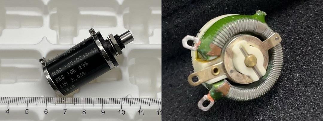
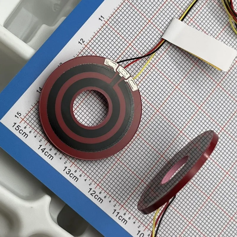
2.4 Mixing different resistive element materials (not common, but worth discussing)
Common resistive element routes can be grouped into three types:
- Carbon film: Cost-friendly, good for general control.
- Conductive plastic: Better for stability, life, and low contact noise needs.
- Cermet / ceramic thick film: Good stability and environmental resistance. Often used when long-term drift and environmental adaptability matter more.
Many people ask about mixing. In theory it can be done, but it can bring material compatibility issues, assembly stress, and stability differences under thermal cycling.
At least in the projects I have seen so far, I have not met a customer who clearly required “material mixing.” If we meet such a request in the future, we will evaluate feasibility and risks based on facts, because it often means a more complex multi-circuit linkage need.
3) How we handle customer requirements
I usually confirm requirements in three steps:
Step 1: Basic targets, such as angle, length, temperature range, and life.
Step 2: Confirm hard limits, such as installation dimensions, and whether a specific material is mandatory. At the same time, we may give practical suggestions based on the customer’s goals, such as lower cost or shorter lead time. We confirm priorities together, so the project does not go back and forth later.
Step 3: Based on the customer’s drawings/specs, we prepare a production-line spec, confirm the final details with the customer, and then move to the next process.
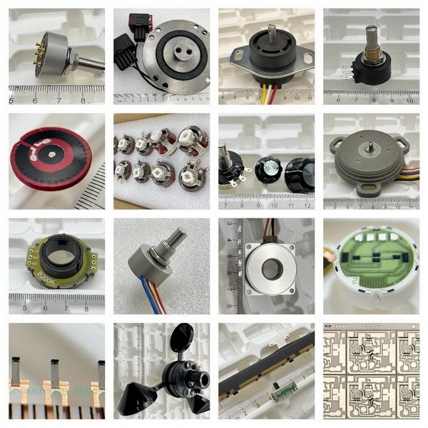
4) Typical application scenarios (grouped by function)
I hesitated about whether to include this section, but I will still share a general view.
Some customers do not share photos of the application and installation location. They only ask us to copy the sample. We understand that, so I will keep it general here.
Below I match “scenario” with “material route,” so you can quickly judge what each gang may need (final choice still depends on drawings/specs):
| Scenario type | What this type usually cares about | Material tendency I see more often (carbon film / conductive plastic / cermet) | Notes |
|---|---|---|---|
| Panel control | Simple operation, balance of cost and stability | Carbon film or cermet is common. If adjustment is frequent and feel/noise matters, conductive plastic is considered more. | Often “good enough + easy assembly,” not extreme matching. |
| Military / aerospace | Reliability, long-term drift, isolation margin | Conductive plastic or cermet is more common. High-performance carbon film appears when targets are milder. | “It fits” is not the same as “stable long term.” Environment and insulation level must be clear. |
| Industrial control | One channel for control, one for monitoring/feedback. Synchronized but different goals. | Main gang often uses conductive plastic/cermet. Support gangs may use carbon film to balance cost. | This fits the “main gang + support gang” approach to reduce risk. |
| Audio (pro: mixer / preamp / amplifier, etc.) | Feel, low noise, channel consistency, long-term reliability | Conductive plastic is common. If long-term drift and harsh environment matter, cermet can be considered. Carbon film is more for cost-driven or milder targets. | Often also cares about Audio/Log taper and tracking target. |
| Audio (consumer: home knobs / panel control, etc.) | Cost, feel, low noise, basic consistency | Carbon film is common. Conductive plastic is considered more when noise/life requirements are higher. Cermet can be used for harsher environment and drift control. | Focus is often “good enough + stable feel.” Matching target should be clarified. |
| Measurement / instrument panel (multi-parameter linkage) | Repeatability, stability, low noise, traceability | Conductive plastic is common. Cermet can be used when drift and environment resistance are priority. | This type of linkage is more functional. Stability is usually ranked higher. |
Final Notes
I probably will not write about multi-gang potentiometers again in the short term, unless I run into some interesting products.
In my view, if a single-gang potentiometer and its components can be made, then stacking multiple gangs is more a test of mechanical control than the potentiometer technology itself. Still, I look forward to unusual custom replacement requests. Even if we may not meet every requirement, seeing product designs I have not seen before is one of the joys of this work.