Skip to content
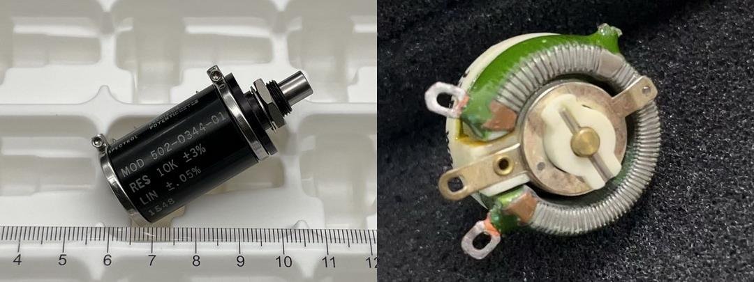
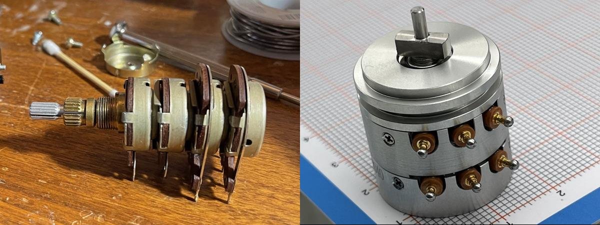
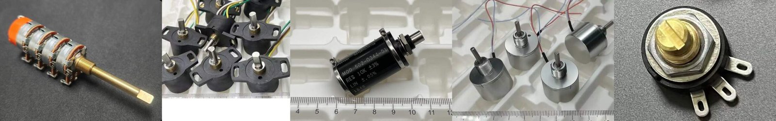
As shown above, this image compares two typical rotary wirewound parts: the left is a Bourns 10-turn precision wirewound potentiometer for repeatable fine adjustment; the right is a Vishay single-turn wirewound power unit with a fired-glaze insulation system and a mechanical stop, commonly used for load adjustment and long-term locked operation where dielectric strength matters.
Wirewound potentiometers originally started from linear motion concepts. But today I do not want to write about the linear type, because it would pull us all the way back to the earliest carbon-pile models. For modern industry, the history is only about two hundred years, but it still feels like a very long story.
So this article only discusses the more common rotary (circular) wirewound structures. For rotary wirewound elements, the most straightforward classification is to split them into two types first: single-turn and multi-turn. In this article, I will also include two relatively “extreme” customer cases, mainly to show how these two types diverge into different application domains.
1. Single-turn Wirewound Potentiometers
The core feature of a single-turn unit is simple: the wiper completes the adjustment within one rotation. It is often used in scenarios where you “set to a point, then lock it for long-term operation.” For further classification, a practical way is to look at power rating + application purpose.
Single-turn parts appear in many engineering situations, but the most common can be grouped into two categories: high-power load adjustment and low-power signal setting. Other uses, such as manual control knobs and service/maintenance adjustment, usually fit as extensions of these two categories.
1.1 Common Use Map for Single-turn (Table)
| Use Direction | What It Looks Like | Typical Scenarios (Examples) | Key Concerns |
|---|---|---|---|
| High-power load adjustment | Adjustable power resistor (Rheostat) | Current sharing, current limiting, load matching, power distribution, voltage drop adjustment | Temperature rise & thermal path, current path, dielectric withstand, locking structure |
| Low-power signal setting | Setpoint / voltage-divider element | Threshold setting, ratio setting, reference voltage setting, simple calibration point | Stability, repeatability, long-term drift & noise |
| Manual operation control | Knob control input | Manual adjustment of output ratio / speed / brightness (wirewound may be used in some cases) | Feel, stability, misuse risk, life |
| Service / maintenance adjustment | Service adjustment part | Field service / debugging: set quickly and lock | Repeatability, reliable locking, environment robustness |
| Low-ohm high-current adjustable segment | A sub-case of load adjustment | Ohm-range resistance, amp-level current load adjustment | Heating, terminal/contact temperature rise, dielectric boundary |
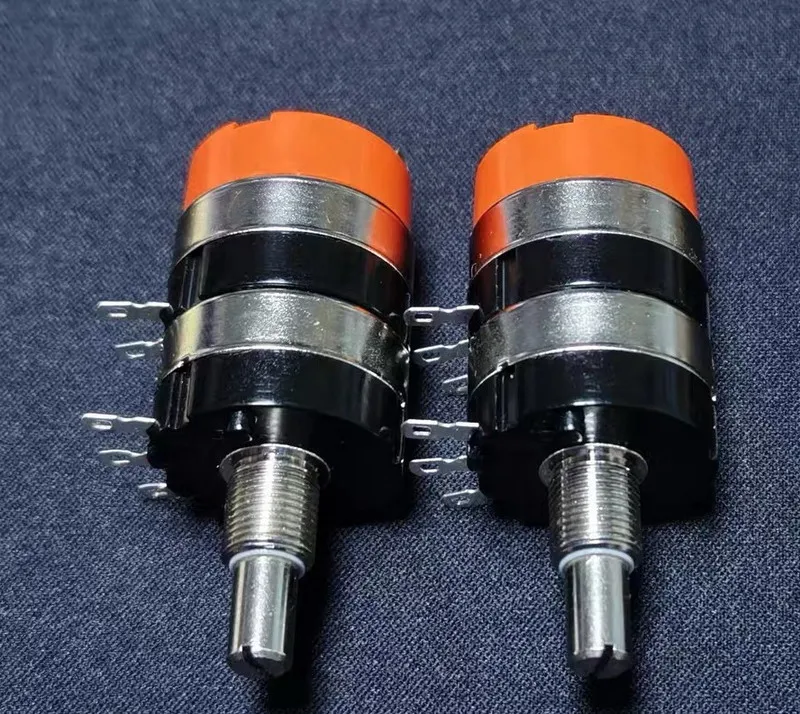
1.2 Customer Case 1: Single-turn High-power Wirewound Adjustable Resistor (Load + High Withstand Voltage)

The figure above is the product specification provided by the customer.
The drawing information is a typical profile of a “single-turn high-power load” part:
- 13Ω, 12.5W
- Adjustable range: 1.75Ω to 13Ω (adjustable at any position in between, and lockable for long-term operation)
- Built-in stop point: 1.75Ω (with a tolerance window)
- Max current: about 1.55A (near 1.75Ω)
- Ambient temperature: -50°C to 70°C
- Dielectric withstand to ground: 2500 VAC / 60s
- Contact material: silver
This product looks like a potentiometer, but in the system it behaves more like an “adjustable power resistor.” It is often used for long-term load conditions such as current distribution, voltage drop adjustment, and load matching.
1.2.1 A Key Fork for Single-turn Power Parts (Withstand Voltage May Lock the Process Route): Insulation System and Dielectric Level (Clay vs High-temperature Fired Glaze)
When the requirement reaches 2500VAC / 60s (to ground), the insulation system often becomes a critical fork that drives the manufacturing route. Based on common process routes and the practical differences you highlighted, the contrast can be described as:
-
Clay + low-temperature curing (~100°C, about ten minutes): lower cost, and the upper limit of withstand voltage may land around the ~2000V class.
Here is a funny story. A young engineer once suggested, right after joining the factory: “Why don’t we use resin as a coating? It can look like a glaze, it is prettier, and it may reduce the moisture absorption of clay in humid environments. Customers might like it.”
His master replied: “Under high power, if the temperature rises, what do you think will happen? The resin will soften, fall off into fragments, and create unnecessary trouble in the control system. And it still cannot stop the clay from continuing to absorb moisture.”
Unfortunately, that young engineer was me.
-
High-temperature fired glaze (glazed insulation system, fired at high temperature): heavier process and higher cost, and it more commonly matches the ~2500V class withstand voltage requirements.
1.2.2 Why the Customer Repeatedly Emphasizes the 1.75Ω Mechanical Stop Point
Many Western customers may assume certain mature processes as “standard practice in the supply chain,” but they can be much more sensitive to details like “mechanical stop + resistance window,” especially if they believe it has not been validated during outsourced production and it can affect adjustment boundaries.
For the factory, the key is to define the stop-point related requirements clearly:
- Position/angle tolerance of the stop point
- Resistance window near the stop point (allowable range around 1.75Ω)
- Repeatable measurement points and acceptance method
1.3 Comparison Table of Two Customer Cases: Single-turn Power Part vs Multi-turn Precision Part
| Item | Case 1: Single-turn High-power Wirewound Adjustable Resistor (Power/Load) | Case 2: Multi-turn Precision Wirewound Potentiometer (Setting/Measurement) |
|---|---|---|
| Category | Single-turn | Multi-turn |
| Typical role | Adjustable power resistor (Rheostat) | Precision setting element / displacement measurement element |
| Key parameters (from cases) | 13Ω, 12.5W; adjustable 1.75Ω–13Ω; 2500VAC/60s to ground; 1.75Ω mechanical stop (window) | 2W@70°C; 200Ω–100kΩ; linearity ±0.25%; TCR ≤±50×10⁻⁶/K; effective electrical travel 7200° (-4/+4°); mechanical endurance 5000 cycles; M10×0.75; solder terminals |
| Most common uses | Current sharing/control, load adjustment, power distribution, set-and-lock long-term operation | Precision setting and repeatable fine adjustment; draw-wire displacement sensing (linear motion → rotation → voltage output) |
| Manufacturing focus (priority) | Withstand/insulation system → temperature rise & thermal path → stop window & locking structure | Travel & stability metrics (linearity/TCR/noise) → end window → endurance & assembly consistency |
2. Multi-turn Wirewound Potentiometers
The core feature of a multi-turn unit is that the wiper needs many turns to travel from one end to the other. In engineering practice, its applications can be more clearly split into three directions.
2.1 Three Common Application Directions for Multi-turn (Table)
| Application Direction | Typical Target | Typical Examples |
|---|---|---|
| Precision setting / calibration | setpoints, thresholds, gain/offset | instrument calibration, multi-turn trimming, process setpoints |
| Rotary position / angle feedback | shaft angle, rotary position | rotary mechanism feedback, angle measurement/readback |
| Linear displacement measurement | linear distance | draw-wire displacement sensor (linear motion → drum rotation → potentiometer output) |
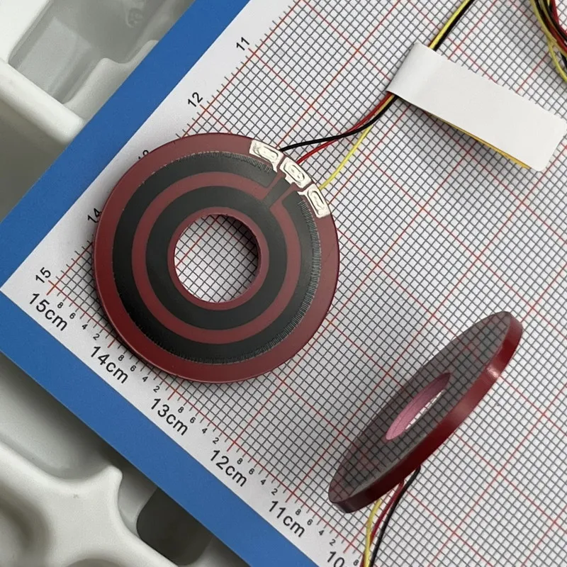
2.2 Customer Case 2: NOL2220 Multi-turn Precision Wirewound Potentiometer (For Draw-wire Displacement / Precision Setting)

The figure above is the product specification provided by the customer.
This specification is a typical “multi-turn precision” profile. The key indicators focus on stability and repeatability:
- Model / power: NOL2220 / 2W (70℃)
- Resistance range: 200Ω–100kΩ, tolerance ±5 (J)
- Temperature coefficient (TCR): ≤±50×10⁻⁶/K
- Element limiting voltage: 300V
- Withstand voltage (DC or AC peak): normal atmosphere 640V; low pressure (8.5kPa) 300V
- Linearity: ±0.25%
- Starting torque: (3–10) mN·m; end-stop torque: 300 mN·m
- Effective electrical travel: 7200° (-4 / +4°)
- Mechanical endurance: 5000 cycles
- Mounting & terminals: bushing thread M10×0.75 (with internal-tooth washer and nut); terminals are solder type
In a draw-wire displacement system, the typical chain is: linear motion → drum rotation → potentiometer output change. The value of a multi-turn unit is that it is easier to use more effective electrical travel, so the output change becomes finer. However, the final system accuracy still depends on the drum backlash, wire elongation, spring tension, structural assembly, tolerance stack-up, and the overall signal processing method.
3. A Factory’s Real Workflow When Receiving a Specification: Make It Manufacturable First, Then Infer Use, Then Match Budget
When receiving a drawing/specification, the internal workflow is usually:
-
Make the function manufacturable first
For example: How does low resistance + high current flow? How to control temperature rise? How to build the insulation system for 2500VAC to ground? How to define the stop point and the resistance window? First, clarify “how to build it.”
-
Infer the actual application use
Map the parameters and structural features to typical system roles: load adjustment, precision setting, rotary feedback, linear displacement measurement, etc.
-
Provide rational options based on the customer’s budget
The same functional goal may have different process routes and cost structures. Budget differences lead to different recommendations. But key clauses (withstand voltage, windows, thermal limits, endurance) should be clarified early to avoid misunderstandings later.
Final Note
Wirewound potentiometers are a mature product family, but in real engineering practice, the “single-turn vs multi-turn” split is still the fastest way to connect classification back to real use. By mapping two real customer cases to the two major types, and then splitting multi-turn applications into three directions (setting / rotary feedback / linear displacement), it becomes easier to build a clear and practical classification intuition.
When NOLELC engineers analyze a project, we usually start by breaking down the hardest constraints in the specification (withstand voltage, temperature rise, travel, windows, endurance). Then we place the selectable process routes and cost structures on the table, so customers can make decisions based on “requirements + budget,” instead of replying “we can’t do it” purely by experience or intuition.