Skip to content
This page helps buyers decide in 2 minutes, and gives engineers the depth to deliver.
1) Quick Selection
Contact allowed?
No → non-contact (Magnetostrictive / LVDT / Optical). Yes → Potentiometric (most economical).
Stroke & life:
Long stroke or >50 M cycles → Magnetostrictive / TLH (rodless track) / LVDT; <5 M & manual control → Potentiometer.
Accuracy target:
≤0.05%FS → Magnetostrictive / LVDT; ≤1%FS → Potentiometer.
Environment & mounting:
Oil/hydraulic → Magnetostrictive; no rod clearance / side-driven guide → TLH; Dust → sealed profile; EMI → 4–20 mA / SSI.
Interface already used:
0–10 V / 4–20 mA / SSI / CAN / Modbus-RTU.
2) Quick Comparison Table
| Type | Best For | Typical Stroke | Accuracy (typ.) | Lifetime | Interfaces | Cost |
|---|---|---|---|---|---|---|
| Magnetostrictive (rod/profile) | Hydraulic cylinders, harsh env., long life | 50–2000 mm | ±0.01–0.05%FS | 100 M+ (non-contact) | 0–10 V / 4–20 mA / SSI / CAN | $$$ |
| LVDT | Precision gauges, aerospace/industrial | 1–300 mm | ±0.25–0.5%FS | 50 M+ | Analog (demod), some digital | $$ |
| Rod-type potentiometric (LWH) | General industrial rod-type, direct absolute measurement | 75–900 mm | ±0.05–0.1%FS (up to ±0.04%FS on longer strokes) | 100 M movements | 0 to voltage supplied (ratiometric) | $$ |
| Rodless profile potentiometric (TLH) | Long guided motion, no rod clearance, side-driven mounts | 100–3000 mm | ±0.05%FS (up to ±0.02%FS) | 100 M+ | 0 to voltage supplied (ratiometric) | $$ |
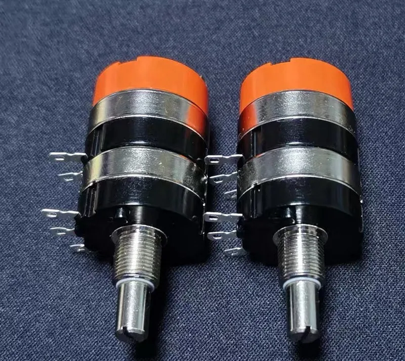
| Linear potentiometer (manual/motorized) | Faders/HMI, cost-sensitive set-points | 10–300 mm | ±0.5–1.0%FS | 1–5 M cycles | Ratiometric voltage | $ |
Note on LWH and TLH: Both rod-type (LWH) and rodless profile (TLH) belong to the potentiometric family. They still use a resistive track and a moving wiper, but are built as industrial-grade displacement transducers for long strokes and closed-loop feedback. This is why datasheets often call them “transducers,” even though their core principle is potentiometric.
3) Match to NOLELC Families
- Hydraulic cylinders / oil & shock → Magnetostrictive LDT (rod-in-cylinder / profile).
- Injection molding:
• Clamping/tie-bar, short-to-mid strokes (≤900 mm) with rod clearance → Rod-type potentiometric (LWH).
• Long platen travel or side-driven guide (up to 3,000 mm) or no rod space → Rodless profile potentiometric (TLH) (or profile magnetostrictive if non-contact required). - Tight spaces / portable devices → Mini non-contact LDT.
- Human-in-the-loop control → Linear potentiometer (manual or motorized).
4)——— Advanced Explainer ———
4.1 Sensor vs Transducer — Clear Definitions
A transducer converts energy; a sensor is a transducer that detects a stimulus and outputs a usable signal.
In practice, “LDT” ≈ “linear displacement sensor”. We use Sensor as the primary term and include LDT for completeness.
4.2 Core Technologies & How They Work
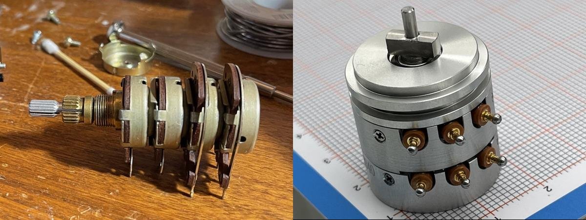
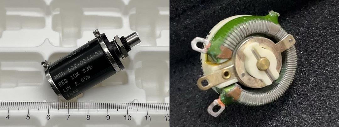
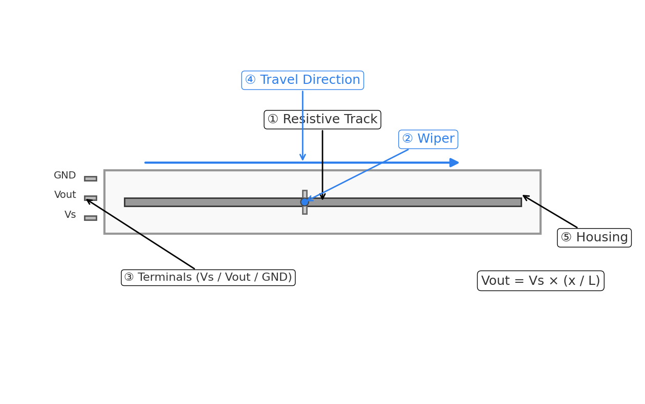
4.2.1Potentiometric Linear Sensor (Resistive)
A resistive element and a moving wiper form a divider: Vout = Vs × (x/L) + error. Form factors include rod-type (e.g., LWH) and rodless profile track (e.g., TLH); both are contact-type and output ratiometric voltage.
Pros: simple, low cost, easy ADC read. Cons: wear/contamination, limited life.
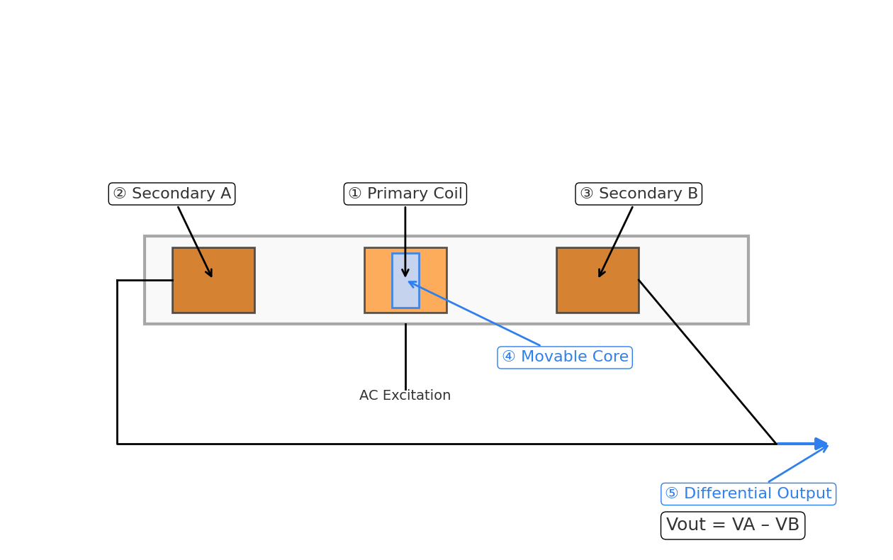
4.2.2 LVDT (Linear Variable Differential Transformer)
AC-excited primary; two secondaries; movable core shifts coupling; phase-sensitive differential output around null.
Pros: no wear, excellent repeatability, low drift; Cons: needs conditioning electronics.
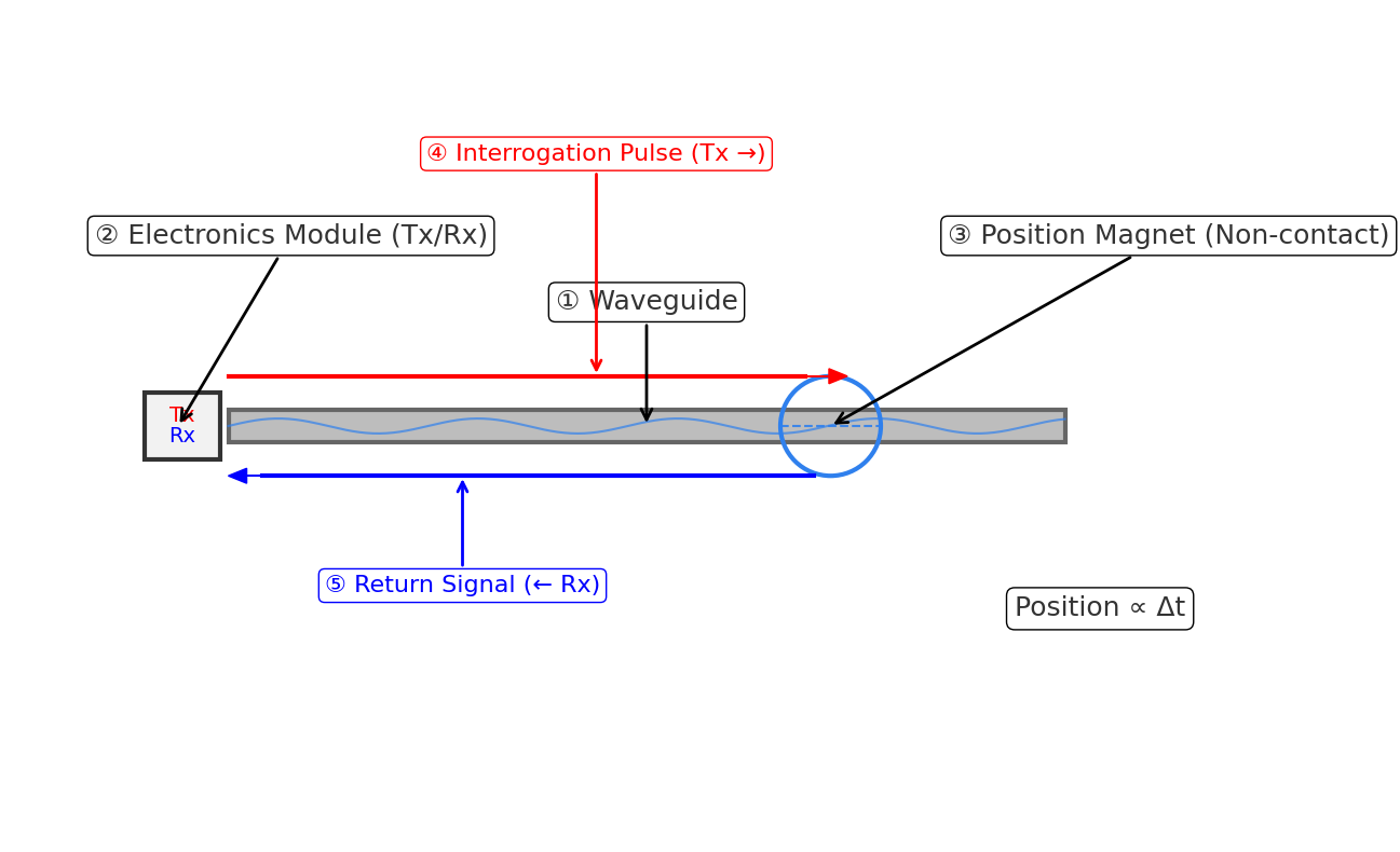
4.2.3 Magnetostrictive (Rod/Profile)
A current pulse interacts with a position magnet along a waveguide; time-of-flight of the torsional wave ∝ distance.
Pros: non-contact, long life, ideal for hydraulic cylinders; Cons: higher cost, EMI-aware routing.
4.3 Key Specs — What They Really Mean (Full)
Accuracy = max absolute error vs. true position.
Linearity = deviation from best-fit straight line.
Resolution = smallest detectable step.
Repeatability = same-point spread.
Hysteresis = forward vs. reverse difference.
Typical ranges by technology (as % of full scale, %FS):
• Potentiometric: ±0.5–±1.0%FS
• LVDT: ±0.25–±0.5%FS
• Magnetostrictive: ±0.01–±0.05%FS
What does %FS mean? “%FS” is the percentage of full scale (FS), where FS is the rated travel of the sensor. “±0.5%FS” means the max error is ±0.5% of the full travel.
Full-Scale Error Examples
| Full Scale (FS) | ±0.5%FS | ±1.0%FS | ±0.25%FS | ±0.05%FS | ±0.01%FS |
|---|---|---|---|---|---|
| 100 mm | ±0.5 mm | ±1.0 mm | ±0.25 mm | ±0.05 mm (50 μm) | ±0.01 mm (10 μm) |
| 500 mm | ±2.5 mm | ±5.0 mm | ±1.25 mm | ±0.25 mm (250 μm) | ±0.05 mm (50 μm) |
Use the row matching your stroke to estimate practical error for each technology tier.
4.4 Selection Decision Tree (Detailed)
Contact → Stroke & Life → Accuracy → Interface → Environment/IP → Mounting space → Cost target.
4.5 Error Budget (Practical)
Worst-case: |Total| ≤ |linearity| + |repeatability| + |temp drift| + |mounting run-out| + |electronics|.
Statistical (preferred): σ_total ≈ sqrt(σ_lin² + σ_rep² + σ_temp² + σ_elec²); add mounting as fixed bias.
4.6 Potentiometer vs Sensor — Use Each Where It Shines
Use linear potentiometer for human-in-the-loop control (mixers, motorized faders, simple set-points) and tight budgets.
Use LDT sensors for automated feedback, long life, harsh environments, or when digital buses (CAN/SSI) are needed.
— End —