Skip to content
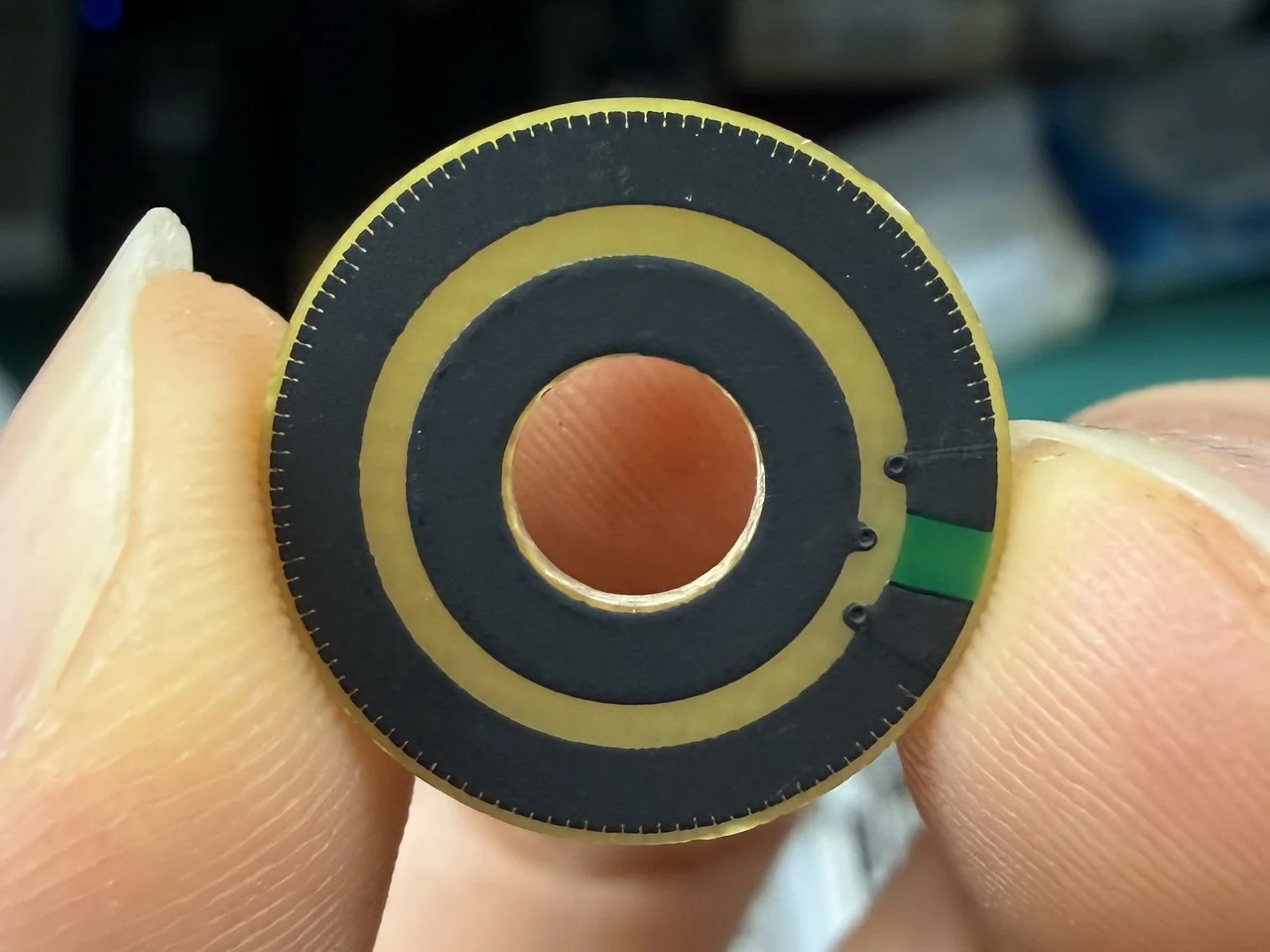
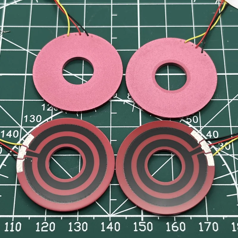
13.6 mm outer diameter circular carbon film resistive element sample after linearity and resistance trimming, with about 0.25% linearity and 50 to 100 mV CRV at 5V input.
Introduction
Recently, I met a custom project customer who was especially concerned about the CRV and linearity of a circular membrane resistive element. His idea was very direct. He wanted to make 20 to 30 sample sets first, test them, and then decide what to do next.
But after I recalculated the full development path, I found that if we reopened the substrate tooling, the screen printing template, and the matching wiper tooling just for this small sample quantity, it would not be very reasonable, no matter whether the customer paid the full cost or we paid for it ourselves.
So we proposed an alternative test plan:
First, we use our existing complete tooling set to verify the performance. After the test result is accepted, the customer can then decide whether to open formal tooling with us and move to mass production.
When I talk about this kind of performance testing, I usually remind the customer of one thing first:
It is better to test the complete set.
The reason is practical. The test result of a contact potentiometer is not decided only by the resistive element itself. The contact condition of the wiper also directly affects the result.
If the customer uses our resistive element but tests it with another supplier’s wiper, the final linearity and CRV result may not truly represent the actual performance of our product itself.
Basic Product Requirement Information
The starting point of this discussion is very clear.
The customer’s design structure has already been fixed. In other words, the customer already has a clear idea of the product structure, functional direction, and key performance points. If the test result is acceptable, we will still need to open formal tooling based on the customer’s own size and structure later.
But at the current stage, what the customer wants to confirm first is:
- The linearity performance of this route
- Whether the CRV is within an acceptable range
- Whether this factory’s manufacturing capability is worth further investment
At the same time, we really do not have an existing substrate for this outer diameter, we do not have the matching screen printing template, and we also do not have an existing mold for the matching wiper of this product.
To be honest, the wiper mold is often the most expensive part in the full set.
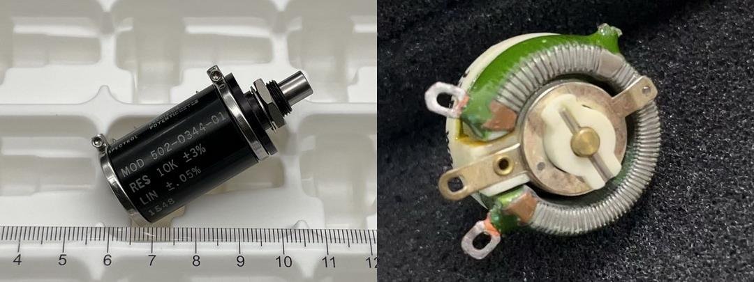
First, here are some basic conditions. The approximate resistive track information of the customer’s resistive element and our existing resistive element is shown below:
The left image is the customer’s target product, with a total resistance of 10kΩ. At this stage, the customer is mainly focused on linearity and CRV.
Based on the information above
In this circular equivalent test, the first thing we lock is the travel, which means the effective arc length.
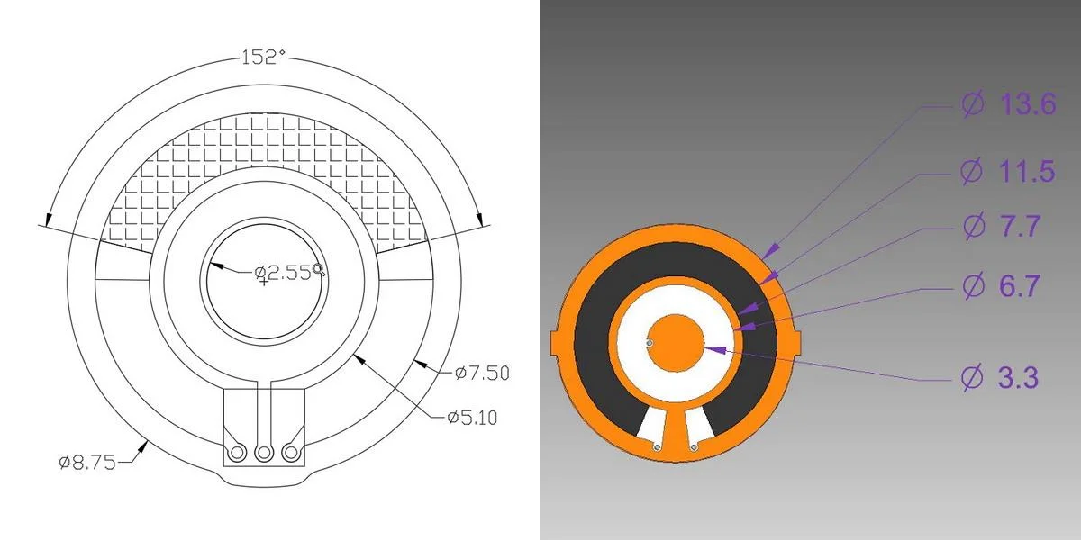
The carbon track required by the customer is:
- Outer carbon track diameter: Ø8
- Inner carbon track diameter: Ø5
- Effective angle: 152°
First, calculate the center diameter of the track:
D₁ = (8 + 5) ÷ 2 = 6.5 mm
If written as the center radius, it becomes:
r₁ = 6.5 ÷ 2 = 3.25 mm
The original effective arc length formula is:
L = π × D × θ ÷ 360
Substitute the customer data:
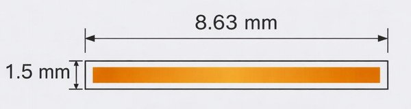
L₁ = π × 6.5 × 152 ÷ 360 ≈ 8.63 mm
That means the customer’s 152° requirement is essentially equal to an effective running arc length of about 8.63 mm.
This point is very important to me. What I care about more is not whether the angle number looks exactly the same, but whether the actual effective path traveled by the wiper is still maintained.
If We Change to an Existing Substrate with a Larger Outer Diameter, Why Does the Angle Change?
The carbon track range of our existing complete tooling set is:
- Outer side: Ø11.5
- Inner side: Ø7.7
First, calculate the new center diameter of the track:
D₂ = (11.5 + 7.7) ÷ 2 = 9.6 mm
If written as the center radius, it becomes:
r₂ = 9.6 ÷ 2 = 4.8 mm
If I want the effective arc length on our existing tooling to remain close to the customer’s original design, that means:
L₂ = L₁ = 8.63 mm
Then the corresponding angle must be recalculated:
θ₂ = L₂ × 360 ÷ (π × D₂)
Substitute the data:
θ₂ = 8.63 × 360 ÷ (π × 9.6) ≈ 103°
That means if I only require equivalent arc length, then the customer’s original 152° will become about 103° after moving to this larger existing tooling.
Our idea is not to make the angle number identical. Our priority is to keep the effective path length close.
Question 1: The Angle Changed, So the Resistance per Degree Also Changed. How Can the Test Still Be Valid?
When people see this, their first reaction is usually:
It was 152° before, and now it becomes 103°. So the resistance within each degree has changed too, right?
For example:
- 10k ÷ 152 ≈ 65.8 Ω/°
- 10k ÷ 103 ≈ 97.1 Ω/°
This surface-level change does exist.
But in this equivalent test, I do not focus first on how many ohms each degree represents. Instead, I first treat this resistive track as a linear resistive film with a fixed length.
Because once I lock these two points first:
- The effective travel length is still 8.63 mm
- The total resistance is still 10kΩ
Then the target resistance per unit length is already fixed:
10,000 ÷ 8.63 ≈ 1159 Ω/mm
In other words, what we really want to hold first is:
- Effective path length
- Total resistance
- Resistance target per unit length
As for how to achieve this target later, whether by material ratio adjustment, process adjustment, or trimming, that is an internal factory problem to solve. It is not a reason to reject the equivalent method itself from the beginning.
Question 2: The Track Width Changed. Will That Affect the Meaning of the Linearity and CRV Test?
The track width in the customer’s drawing is about:
W₁ = (8 - 5) ÷ 2 = 1.5 mm
The track width in our existing tooling is about:
W₂ = (11.5 - 7.7) ÷ 2 = 1.9 mm
Many people will continue to ask:
If the track width changes from 1.5 mm to 1.9 mm, is the test result still reliable?
This question cannot be answered by simply saying it is exactly the same, and it also cannot be answered by saying it has no meaning at all.
First, Look at Linearity
Linearity is essentially a percentage index relative to the full travel, for example ±0.5%.
So as long as the effective travel is still maintained, what I care about more is whether the resistance distribution along this path can still be controlled.
In other words, as long as the total resistance and the resistance per unit length within this equivalent travel can still be controlled stably, then even if it comes from a track with a different width, the early trend judgment of linearity still has reference value.
I would not say this equivalent method can 100 percent replace a formal final-size sample. But at least in the early judgment stage, it does not automatically lose its value just because the track width is different.
Then Look at the Conductive Path and CRV
As for the conductive path, the actual current distribution will of course not be a completely ideal average state.
But in this kind of early equivalent judgment, what I care about more is not how to imagine the local current path, but whether:
- The effective path is still maintained
- The resistance per unit length can still be controlled
- The total resistance can still be brought back to the target range
- The matching relationship between the wiper and the resistive track is still complete
If these key variables are still within a reasonable range, then the issue caused by the width change is more about how the factory adjusts the carbon paste system and sheet resistance. It does not directly mean the sample loses its early test value in linearity and CRV.
After the Width Changes from 1.5 to 1.9, What Really Needs to Be Adjusted Is the Sheet Resistance of the Carbon Paste System
This is a very important part of the whole article.
The approximate resistance relation can be written as:
R = Rₛ × L ÷ W
Here:
- R is total resistance
- Rₛ is sheet resistance
- L is effective length
- W is track width
If I now require:
- L is still 8.63 mm
- R is still 10kΩ
Then when W changes from 1.5 mm to 1.9 mm, what really needs to change is Rₛ, which means the sheet resistance of the carbon paste system.
Their approximate ratio can be written as:
Rₛ₂ ÷ Rₛ₁ = W₂ ÷ W₁ = 1.9 ÷ 1.5 ≈ 1.27
That means if the track becomes wider, but I still want to bring the resistance per unit length and the total resistance back to the original target, then in theory I need to increase the sheet resistance through the carbon paste system by about 27%.
This calculation is exactly why we believe:
Even if the track width is different, as long as the sheet resistance can be adjusted reasonably, the early trend test of linearity and CRV still has practical reference value.
Why We Still Suggest That Customers Test the Complete Set Whenever Possible
At this point, I still want to emphasize this again:
The customer is currently focused on linearity and CRV.
And these two indexes are closely tied to the contact relationship.
After the wiper is installed, the result will still be affected by several factors, including but not limited to:
- Contact pressure
- Contact area
- Wiper material
- Contact position
- Consistency of the matching structure
So if the resistive element is ours but the wiper is not, then the final linearity and CRV result cannot fully represent the actual performance of our full solution.
That is exactly why the plan I proposed this time is not to just find a similar disk and test it casually. Instead, we try to use an existing complete tooling set that is close to the customer’s size, so the customer can test a sample that is closer to the real contact relationship.
What Stage and Situation Is This Method Suitable For?
I think this method is more suitable for the following stage:
The customer’s design structure has already been fixed.
That means the customer already has a clear idea of the product structure, functional direction, and key performance focus. If the test result is acceptable, then later we will most likely still need to open formal tooling based on the customer’s own size and structure.
But in the early stage, what the customer really wants to confirm first is not the final assembly, but several more practical questions:
- Whether this route has a chance to achieve acceptable linearity
- Whether the CRV is within an acceptable range
- Whether the current material and contact structure are worth further development
- Whether it is worth spending money later on full final-size development
In this situation, if we reopen the substrate, screen printing template, and wiper tooling just for 20 to 30 sample sets, the total cost is usually not reasonable.
What this method solves is not final size confirmation. It solves early performance judgment.
In other words, this step is more like helping the customer judge whether this factory’s manufacturing capability and this product route are worth further investment.
What Still Must Go Back to the Final Drawing?
Since this is an equivalent test, of course it cannot avoid the final product.
If the customer wants to confirm the following items, then we still must go back to the customer’s real required size and structure:
- Final installation size
- Final structure interference
- Final lifetime
- Pre-production samples before mass order
- Final assembly matching
- Final linearity and CRV under stricter conditions
Early judgment cannot replace formal final confirmation.
I would rather say this very directly:
Equivalent testing can help reduce blind investment in the first step, but it cannot replace final development.
Final Notes
The idea of equivalent testing is not to avoid development. It is to solve a more practical problem first:
Can we use the existing complete tooling set to make a solution that still has reference value for linearity, CRV, and part of the basic performance judgment, in a shorter time and at lower cost?
For NOLELC, this is not laziness, and it is not an attempt to bypass formal development. It is more like a practical early-stage judgment method. On the basis of controlling cost as much as possible, we help customers get an earlier understanding of product performance.
Instead of throwing out a full list of tooling prices at the very beginning, I would rather first think clearly about the customer’s real problem and how to verify it in a more reasonable way. For customers, this kind of process is usually easier to accept.
Even if the complete set test passes the customer’s requirement, the customer can still choose to buy only our resistive element and then match it with another supplier’s wiper. These two things do not conflict.